I wanted to have a modern aerodynamics simulator, to test out my flight control hardware and software.
Apologies in advance for a very terse post. I spent a lot of hours in a very short timespan to do this as a quick experiment.
So I used Unreal Engine 4 for the graphics engine, and built on top of that.
The main forces for a low speed aircraft that I want to model:
- The lift force due to the wing
- The drag force due to the wind
- Gravity
- Any horizontal forces from propellers in aircraft-style propulsion
- Any vertical forces from propellers in quadcopter-style propulsion
Lift force due to the wing
The equation for the lift force is:

I created a function for the lift coefficient, 
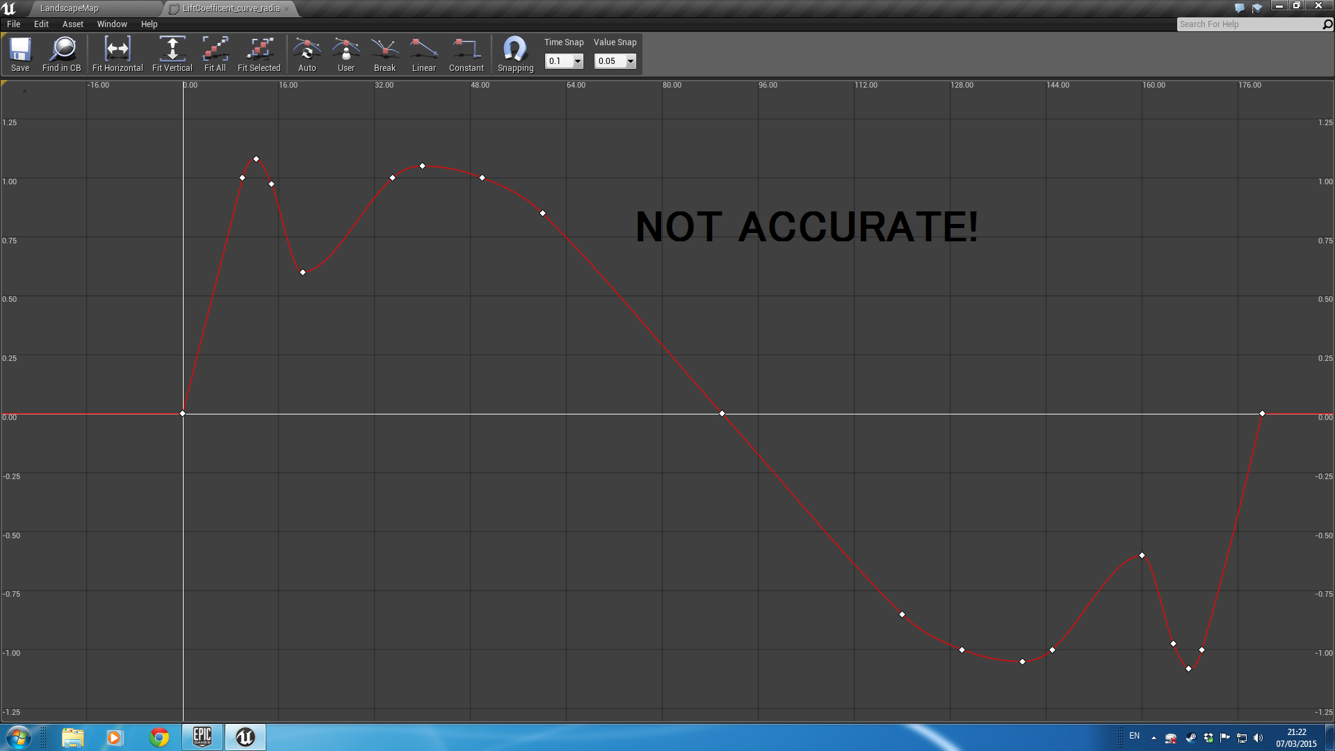
The horizontal axis is the angle of attack, in degrees. When the aircraft is flying “straight”, the angle of attack is not usually 0, but around 5 to 10 degrees, thus still providing an upward force.
I repeat this for each force in turn.
3D Model
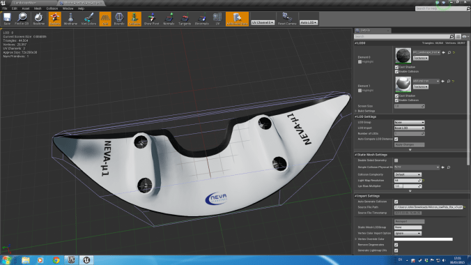
To visualize it nicely, I modelled the craft in blender, manually set the texture space, and painted the texture in gimp. As you can tell from the texture space, there are several horrible problems with the geometry ‘loops’. But it took a whole day to get the top and bottom looking decent, and it was close enough for my purposes.


")
I imported the model into Unreal Engine 4, and used a high-resolution render for the version in the top right, and used a low-resolution version for the game. 
Next, here’s the underneath view. You can see jagged edges in the model here, because at the time I didn’t understand how normal smoothing worked. After a quick google, I selected those vertexes in blender and enabled normal smoothing on them and fixed that.

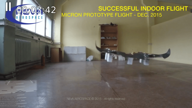
and then finally, testing it out on the real thing:

Architecture
The architecture is a fairly standard Hardware-in-loop system.
The key modules are:

- The Flight Controller which controls the craft. This is not used if we are connected to external real hardware, such as the my controller.
- The Communication Module to the real hardware, receiving information about the desired thrust of the engines and the Radio Control inputs from the user, and sending information about the current simulated position and speed.
- The Physics Simulator which calculates the physical forces on the craft and applies them.
- The User Interface which displays a lot of information about the craft as well as the internal controller.
The low level flight controller and network communication code is written in C++. Much of the high level logic is written in a visual language called ‘Blueprint’.
User Interface
From the GUI User Interface, you can control:
- The aerodynamic forces on the wings
- The height above ground to air pressure curve
- The wing span and aerofoil chord length
- The moment of inertia
- The thrust of the turbines
- The placement of the turbines
- The PID values for the internal controller
Result
It worked pretty well.
PID Tuning
I implemented an auto-tuner for the PID algorithm, which you can tune and trigger from the GUI.
Hardware
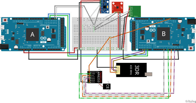
I used two arduinos to control the system:

And set up the Arduinos as so: (Btw, I used the Fritzing software for this – it’s pretty cool).
And putting together the hardware for testing (sorry for the mess). (I’m using QGroundControl to test it out).


And then mounting the hardware on a bit of wood as a base to keep it all together and make it more tidy:

I will hopefully later make a post about the software controlling this.
ESC Motor Controller Delay
I was particularly worried about the delay that the controller introduces.
I modified the program and used a basic UFO style quadcopter, then added in a 50ms buffer, to test the reaction.
For reference, here’s a photo of the real thing that I work on:


The quadcopter is programmed to try to hover over the chair.
I also tested with different latencies:
50ms really is the bare minimum that you can get away with.
These are manually tuned PIDs.
I did also simulate this system in 1D in Matlab’s Simulink:

A graph of the amplitude:

And finally, various bode plots etc. Just click on any for a larger image. Again, apologies for the awful terseness.


