I previously talked about the code for the display driver, and the code for the snake AI algorithm, but here I want to just tie it all together.
I used the arduino tools, setup like so:
I initially made a mistake and used the default 5V option with the 3V board. It uploaded correctly, but the serial output was at half the expected speed. This is because the 5V board runs at 16mhz, but the 3.3V board runs at 8Mhz. (As a side note, I searched for the particle AVR chip and it’s actually rated at 20mhz and 10mhz respectively. I wonder why the Arduino underclocks the processor? As a second side note, for fun I tested a 5V board at 16mhz but actually fed it 3.3V and amazingly it worked. Obviously reliability is probably an issue, but the tolerance for low voltage is well outside the official specs, so in pinch you can really abuse this hardware. I got it down to 3.1V before the 5V board gave up).
Programming for the PC
I wrote the code such that the arduino-specific code was as minimal as possible, and kept in .ino files. And the rest of the code in .cpp files. The result was that I could do almost all the development and debugging for the PC.
Although this was slightly more work (e.g. I had to write an ncurses output), it was very much worth it. I compiled the program with:
The sanitize=address option is new to GCC 4.8.0 and is extremely cool. It’s a memory error checker and it saved my bacon several times. For me, it has replaced valgrind’s memchecker tool.
Monitoring memory usage
I needed to be aware of every byte of memory that I used throughout the project, and to compare my theoretical counting against actual usage I used a pretty neat trick that I found on the internet:
  static int freeRam ()
  {
    extern int __heap_start, *__brkval;
    int v;
    return (int) &v - (__brkval == 0 ? (int) &__heap_start : (int) __brkval);
  }
This function returns the amount of free memory by taking the current stack position (since v is on the stack), and taking the difference to the current heap position. This works because on arduino the heap and stack grow towards each other, like this:
Final product
Final product uses 1.4KB out of the 2KB of memory available.
We need an AI that can play a perfect game of Snake. To collect the food without crashing into itself.
But it needs to run in real time on an 8Mhz processor, and use around 1 KB of memory. The extreme memory and speed restrictions means that we do not want to allocate any heap memory, and should run everything on the stack.
None of the conventional path finding algorithms would work here, so we need a new approach. The trick here is to realise that in the end part of the game, the snake will be following a planar Hamiltonian Cycle of a 2D array:
So what we can do is precompute a random hamiltonian cycle at the start of each game, then have the snake follow that cycle. It will thus pass through every point, without risk of crashing, and eventually win the game.
There are various way to create a hamiltonian cycle, but one way is to use Prim’s Algorithm to generate a maze of half the width and half the height. Then walk the maze by always turning left when possible. The resulting path will be twice the width and height and will be a hamiltonian cycle.
Now, we could have the snake just follow the cycle the entire time, but the result is very boring to watch because the snake does not follow the food, but instead just follows the preset path.
To solve this, I invented a new algorithm which I call the pertubated hamiltonian cycle. First, we imagine the cycle as being a 1D path. On this path we have the tail, the body, the head, and (wrapping back round again) the tail again.
The key is realising that as long as we always enforce this order, we won’t crash. As long as all parts of the body are between tail and the head, and as long as our snake does not grow long enough for the head to catch up with the tail, we will not crash.
This insight drastically simplifies the snake AI, because now we only need to worry about the position of the head and the tail, and we can trivially compute (in O(1)) the distance between the head and tail since that’s just the difference in position in the linear 1D array:
Now, this 1D array is actually embedded in a 2D array, and the head can actually move in any of 3 directions at any time. This is equivalent to taking shortcuts through the 1D array. If we want to stick to our conditions, then any shortcut must result in the head not overtaking the tail, and it shouldn’t overtake the food, if it hasn’t already. We must also leave sufficient room between the head and tail for the amount that we expect to grow.
Now we can use a standard shortest-path finding algorithm to find the optimal shortcut to the food. For example, an A* shortest path algorithm.
However I opted for the very simplest algorithm of just using a greedy search. It doesn’t produce an optimal path, but visually it was sufficiently good. I additionally disable the shortcuts when the snake takes up 50% of the board.
To test, I started with a simple non-random zig-zag cycle, but with shortcuts:
What you can see here is the snake following the zig-zag cycle, but occasionally taking shortcuts.
We can now switch to a random maze:
And once it’s working on the PC, get it working on the phone:
Code
NOTE: I have lost the original code, but I’ve recreated it and put it here:
First, the pin mappings as shown in the previous diagram:
                     // Description  Pin on LCD display
                     // LCD Vcc .... Pin 1 +3.3V (up to 7.4 mA) Chip power supply
#define PIN_SCLK  2  // LCD SPIClk . Pin 2 Serial clock line of LCD                          // Was 2 on 1st prototype
#define PIN_SDIN  5  // LCD SPIDat . Pin 3 Serial data input of LCD                          // Was 5 on 1st prototype
#define PIN_DC    3  // LCD Dat/Com. Pin 4 (or sometimes labelled A0) command/data switch    // Was 3 on 1st prototype
                     // LCD CS  .... Pin 5 Active low chip select (connected to GND)
                     // LCD OSC .... Pin 6 External clock, connected to vdd
                     // LCD Gnd .... Pin 7 Ground for VDD
                     // LCD Vout ... Pin 8 Output of display-internal dc/dc converter - Left floating - NO WIRE FOR THIS.  If we added a wire, we could connect to gnd via a 100nF capacitor
#define PIN_RESET 4  // LCD RST .... Pin 9 Active low reset   // Was 4 on prototype
#define PIN_BACKLIGHT 6 // - Backlight controller. Optional.  It's connected to a transistor that should be connected to Vcc and gnd

#define LCD_C     LOW
#define LCD_D     HIGH
We need to initialize the LCD:
void LcdClear(void)
{
  for (int index = 0; index < LCD_X * LCD_Y / 8; index++)
    LcdWrite(LCD_D, 0x00);
}

void LcdInitialise(void)
{
 // pinMode(PIN_SCE, OUTPUT);
  pinMode(PIN_RESET, OUTPUT);
  pinMode(PIN_DC, OUTPUT);
  pinMode(PIN_SDIN, OUTPUT);
  pinMode(PIN_SCLK, OUTPUT);
  pinMode(PIN_BACKLIGHT, OUTPUT);
  digitalWrite(PIN_RESET, LOW); // This must be set to low within 30ms of start up, so don't put any long running code before this
  delay(30); //The res pulse needs to be a minimum of 100ns long, with no maximum.  So technically we don't need this delay since a digital write takes 1/8mhz = 125ns.  However I'm making it 30ms for no real reason
  digitalWrite(PIN_RESET, HIGH);
  digitalWrite(PIN_BACKLIGHT, HIGH);
  LcdWrite(LCD_C, 0x21 );  // LCD Extended Commands.
  LcdWrite(LCD_C, 0x80 + 0x31 ); // Set LCD Vop (Contrast).  //0x80 + V_op    The LCD voltage is:  V_lcd = 3.06 + V_op * 0.06
  LcdWrite(LCD_C, 0x04 + 0x0 );  // Set Temp coefficent. //0 = Upper Limit.  1 = Typical Curve.  2 = Temperature coefficient of IC.  3 = Lower limit
  LcdWrite(LCD_C, 0x10 + 0x3 );  // LCD bias mode 1:48. //0x10  + bias mode.  A bias mode of 3 gives a "recommended mux rate" of 1:48
  LcdWrite(LCD_C, 0x20 );  // LCD Basic Commands
  LcdWrite(LCD_C, 0x0C );  // LCD in normal mode.
}

/* Write a column of 8 pixels in one go */
void LcdWrite(byte dc, byte data)
{
  digitalWrite(PIN_DC, dc);
  shiftOut(PIN_SDIN, PIN_SCLK, MSBFIRST, data);
}

/* gotoXY routine to position cursor
   x - range: 0 to 84
   y - range: 0 to 5
*/
void gotoXY(int x, int y)
{
  LcdWrite( 0, 0x80 | x);  // Column.
  LcdWrite( 0, 0x40 | y);  // Row.
}
So this is pretty straightforward. We can’t write per pixel, but must write a column of 8 pixels at a time.
This causes a problem – we don’t have enough memory to make a framebuffer (we have only 2kb in total!), so all drawing must be calculated on the fly, with the whole column of 8 pixels calculated on the fly.
Snake game
The purpose of all of this is to create a game of snake. In our game, we want the snake to be 3 pixels wide, with a 1 pixel gap. It must be offset by 2 pixels though because of border.
The result is code like this:
/* x,y are in board coordinates where x is between 0 to 19 and y is between 0 and 10, inclusive*/
void update_square(const int x, const int y)
{
  /* Say x,y is board square 0,0  so we need to update columns 1,2,3,4
   * and rows 1,2,3,4  (column and row 0 is the border).
   * But we have actually update row 0,1,2,3,4,5,6,7  since that's how the
   * lcd display works.
   */
  int col_start = 4*x+1;
  int col_end = col_start+3; // Inclusive range
  for(int pixel_x = col_start; pixel_x <= col_end; ++pixel_x) {
    int pixelrow_y_start = y/2;
    int pixelrow_y_end = (y+1)/2; /* Inclusive.  We are updating either 1 or 2 lcd block, each with 2 squares */
    int current_y = pixelrow_y_start*2;
    for(int pixelrow_y = pixelrow_y_start; pixelrow_y <= pixelrow_y_end; ++pixelrow_y, current_y+=2) {
      /* pixel_x is between 0 and 83, and pixelrow_y is between 0 and 5 inclusive */
      int number = 0; /* The 8-bit pixels for this column */
      if(pixelrow_y == 0)
        number = 0b1; /* Top border */
      else
        number = get_image(x, current_y-1, (pixel_x-1)%4) >> 3;
      if( current_y < ARENA_HEIGHT) {
        number |= (get_image(x, current_y, (pixel_x-1)%4) << 1);
        number |= (get_image(x, current_y+1, (pixel_x-1) %4) << 5);
      }
      gotoXY(pixel_x, pixelrow_y);
      LcdWrite(1,number);
    }
  }
}

int get_image(int x, int y, int column)
{
  if( y >= ARENA_HEIGHT)
    return 0;
  int number = 0;
  if( y == ARENA_HEIGHT-1 )
    number = 0b0100000; /* Bottom border */

  if(board.hasSnake(x,y))
    return number | get_snake_image(x, y, column);

  if(food.x == x && food.y == y)
    return number | get_food_image(x, y, column);

  return number;
}

int get_food_image(int x, int y, int column)
{
  if(column == 0)
    return 0b0000;
  if(column == 1)
    return 0b0100;
  if(column == 2)
    return 0b1010;
  if(column == 3)
    return 0b0100;
}

/* Column 0 and row 0 is the gap between the snake*/

/* Column is 0-3 and this returns a number between
 * 0b0000 and 0b1111 for the pixels for this column
   The MSB (left most digit) is drawn below the LSB */
int get_snake_image(int x, int y, int column)
{
  if(column == 0) {
    if(board.snakeFromLeft(x,y))
      return 0b1110;
    else
      return 0;
  }
  if(board.snakeFromTop(x,y))
    return 0b1111;
  else
    return 0b1110;
}
Pretty messy code, but necessary to save every possible byte of memory.
Now we can call
update_square(x,y)
when something changes in board coordinates x,y, and this will redraw the screen at that position.
So now we just need to implement the snake logic to create a snake and get it to play automatically. And do so in around 1 kilobyte of memory!
The Nokia 6110 phone came with a snake game that was an instant success. Many people bought the phone just to play the game.
I wanted to recreate this game, but have an AI playing it continually.
Final Result
This is the final result that I was aiming for:
Starting
I bought one of these phones from ebay, and took it apart. It comprises of two boards – the top board controls the LCD and the buttons, and uses a ‘springy’ connector to connect to the bottom board.
Bottom Board
The bottom board contains all the phone electronics, including the power connector.
I don’t want to keep any of the phone electronics, so I took out my trusty saw and cut the middle part of the bottom board out, throwing it away and keeping the top most part and the bottom most part:
(Not shown here, but I also cut off the top part, purely for aesthetics, because the antenna pokes through the case).
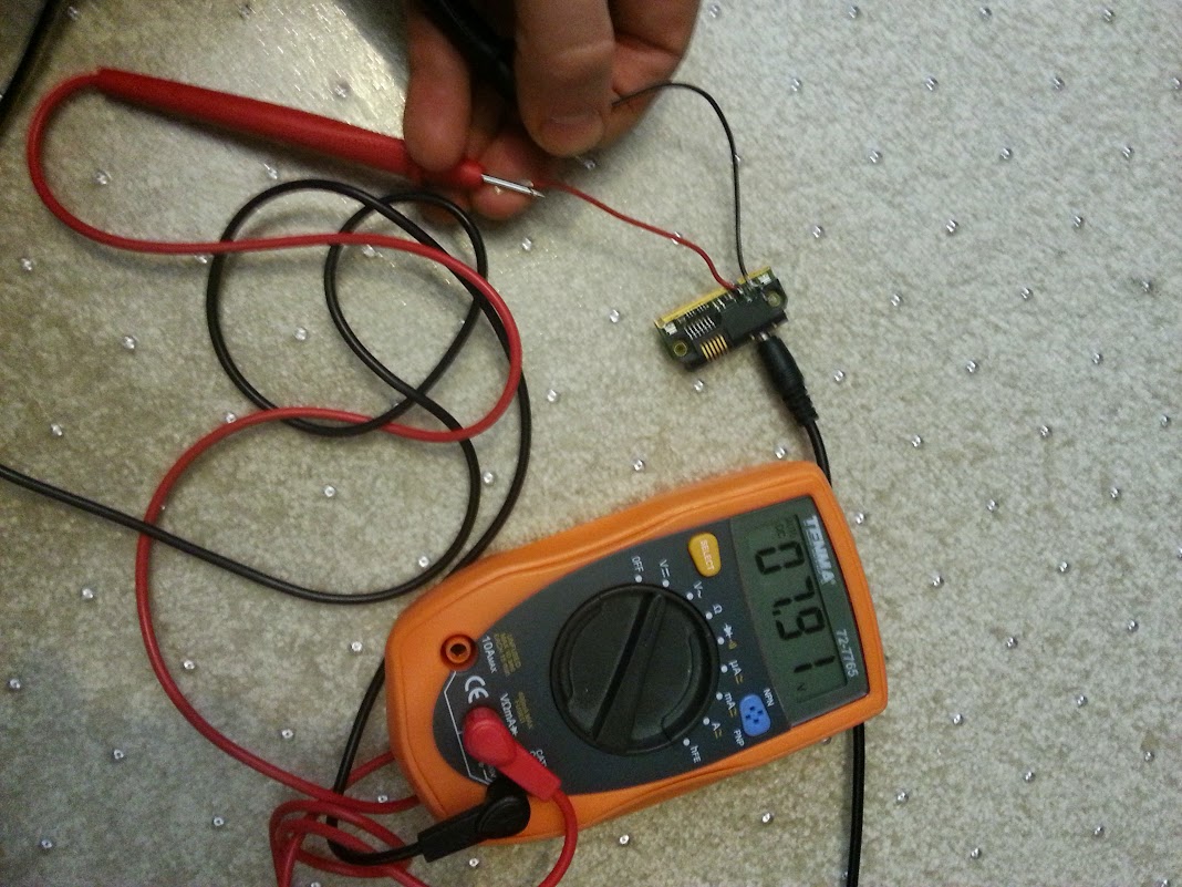
Next, I soldered two wires to the power connector, using a multimeter to determine which wires to connect to.
Now that we have power, it’s time to move on to the top board, and get the LCD connected.
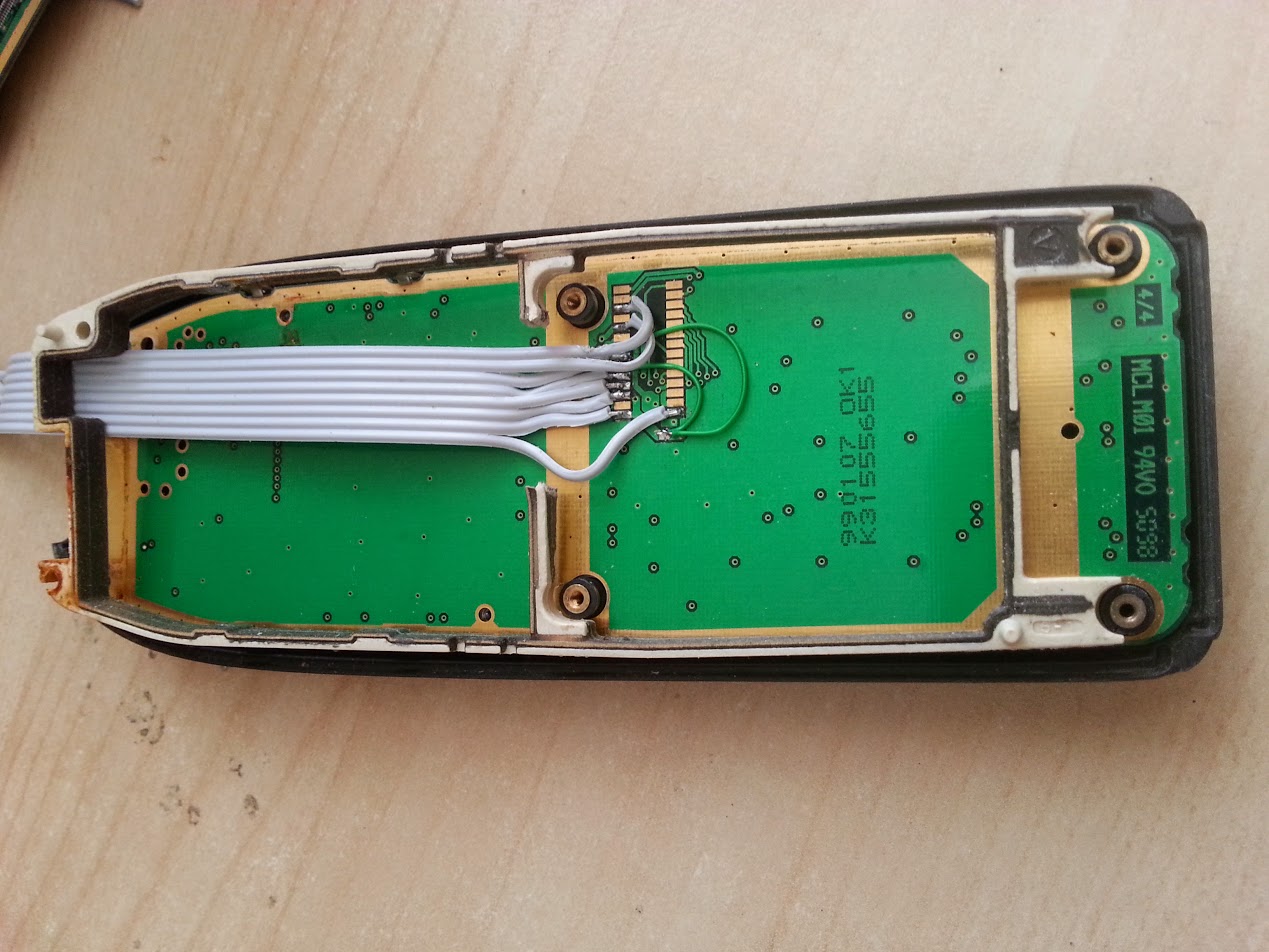
Top board
The LCD connects via a “zebra” connector to the board:
By finding and reading the PDF for this LCD display (pcd8544), we can work out which pins are which. These pins map to the otherside of the board, connecting to the bottom board via the “springy connector” that I labelled in an image above. Using a multimeter, I mapped out the pins. The LED backlights are also helpfully connected here, via a transistor, so those were wired up too:
The blue lines here indicate where I’ve shorted the connections to ground, and the red dotted lines is where I’ve shorted the connections to the power line. In a future version I might leave the LED power separate, and power that separately, bypassing the arduino regulator. The LEDs draw 100mA at 3.3V.
Here’s the final soldered product:
At this stage, I wrapped the board in salotape to provide a small amount of strength and to avoid any short circuits when placing other boards on top.
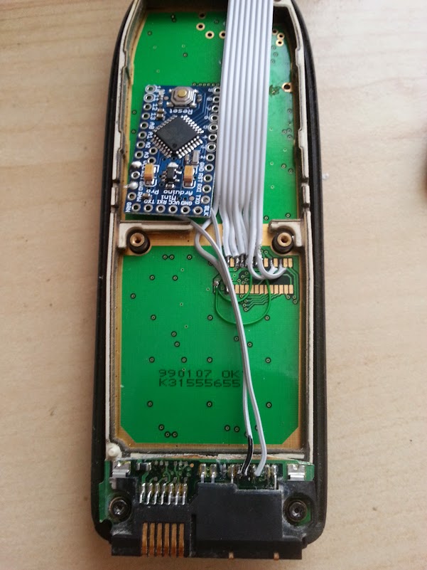
Arduino
In the first iteration of this, I used a 5V Arduino Nano running at 16Mhz, even though the display is supposed to accept only 3.3V logic and power. I looked carefully at the display specifications, and it did appear that it should tolerate 5V. However the result was that the display contrast was wrong. So I switched to a 3.3V Arduino Pro Mini, running at 8 Mhz.
To make it possible to program the Arduino, I cut 6 female dupont leads and soldered them to the FTDI header. This allows me to program the Arduino even when the phone is assembled.
Next I connected up the wires to the arduino pins as marked in the diagram (SCLK=pin2, SDIN=pin5, D/C=pin3, Res=pin4). Optionally the backlight can be connected to pin6, but I hardwired it to power.
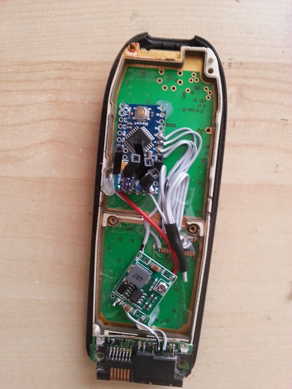
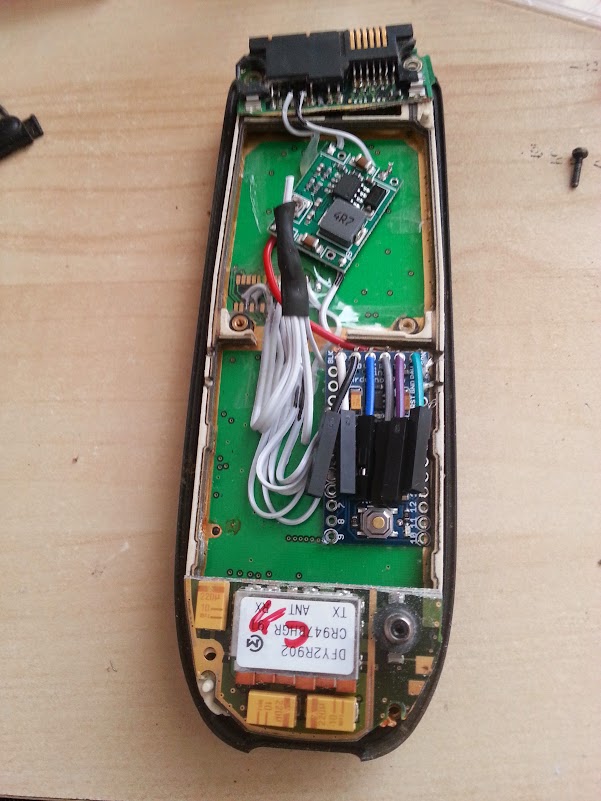
Regulator
In the first iteration of this, I then added an arduino and powered the arduino directly from the 7.9V input. However the arduino’s has a linear regulator, meaning that it was producing (7.9V – 3.3V) * 100mA = 0.5 Watts of heat. I thought that this would be tolerable, but it got a bit too warm for my liking inside the case. So I added a switching regulator to convert 7.9V down to 3.6V, which I then fed to the arduino’s linear regulator.
Top half of the bottom board
Finally, I added the top half of the original board, simply so that the original antenna poked through.
Now the case can be screwed on, and we can start to program it by plugging in an FTDI usb connector: