
This is a four part series:
- Part 1 – Electronics
- Part 2 – Display Driver
- Part 3 – Algorithms
- Part 4 – Programming
The Nokia 6110 phone came with a snake game that was an instant success. Many people bought the phone just to play the game.
I wanted to recreate this game, but have an AI playing it continually.
Final Result
This is the final result that I was aiming for:
Starting
I bought one of these phones from ebay, and took it apart. It comprises of two boards – the top board controls the LCD and the buttons, and uses a ‘springy’ connector to connect to the bottom board.
Bottom Board
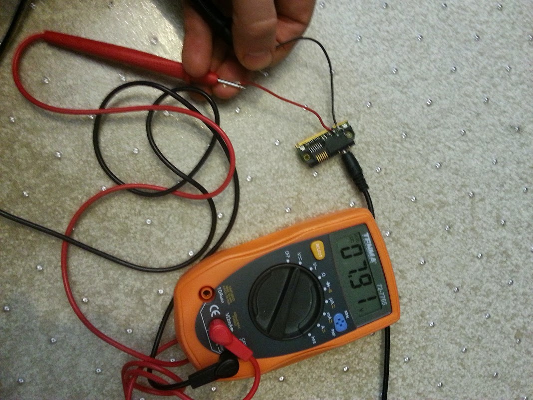
The bottom board contains all the phone electronics, including the power connector.
I don’t want to keep any of the phone electronics, so I took out my trusty saw and cut the middle part of the bottom board out, throwing it away and keeping the top most part and the bottom most part:


(Not shown here, but I also cut off the top part, purely for aesthetics, because the antenna pokes through the case).
Next, I soldered two wires to the power connector, using a multimeter to determine which wires to connect to.
Now that we have power, it’s time to move on to the top board, and get the LCD connected.
Top board
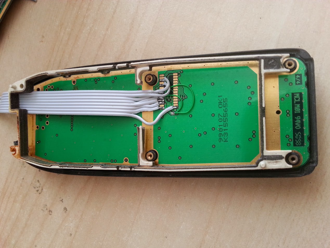
The LCD connects via a “zebra” connector to the board:

By finding and reading the PDF for this LCD display (pcd8544), we can work out which pins are which. These pins map to the otherside of the board, connecting to the bottom board via the “springy connector” that I labelled in an image above. Using a multimeter, I mapped out the pins. The LED backlights are also helpfully connected here, via a transistor, so those were wired up too:

The blue lines here indicate where I’ve shorted the connections to ground, and the red dotted lines is where I’ve shorted the connections to the power line. In a future version I might leave the LED power separate, and power that separately, bypassing the arduino regulator. The LEDs draw 100mA at 3.3V.
Here’s the final soldered product:
 At this stage, I wrapped the board in salotape to provide a small amount of strength and to avoid any short circuits when placing other boards on top.
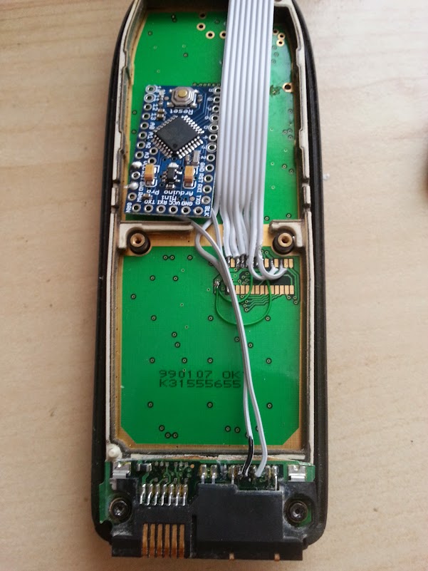
Arduino
In the first iteration of this, I used a 5V Arduino Nano running at 16Mhz, even though the display is supposed to accept only 3.3V logic and power. I looked carefully at the display specifications, and it did appear that it should tolerate 5V. However the result was that the display contrast was wrong. So I switched to a 3.3V Arduino Pro Mini, running at 8 Mhz.
To make it possible to program the Arduino, I cut 6 female dupont leads and soldered them to the FTDI header. This allows me to program the Arduino even when the phone is assembled.
Next I connected up the wires to the arduino pins as marked in the diagram (SCLK=pin2, SDIN=pin5, D/C=pin3, Res=pin4). Optionally the backlight can be connected to pin6, but I hardwired it to power.
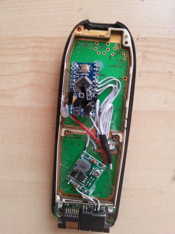
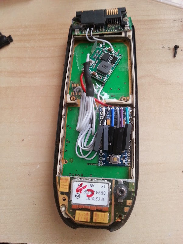
Regulator
In the first iteration of this, I then added an arduino and powered the arduino directly from the 7.9V input. However the arduino’s has a linear regulator, meaning that it was producing (7.9V – 3.3V) * 100mA = 0.5 Watts of heat. I thought that this would be tolerable, but it got a bit too warm for my liking inside the case. So I added a switching regulator to convert 7.9V down to 3.6V, which I then fed to the arduino’s linear regulator.
Top half of the bottom board
Finally, I added the top half of the original board, simply so that the original antenna poked through.
Now the case can be screwed on, and we can start to program it by plugging in an FTDI usb connector:

Next up – Programming it!

Well written
LikeLike