Wire bender

I wanted to bend a large amount of wire for another project.

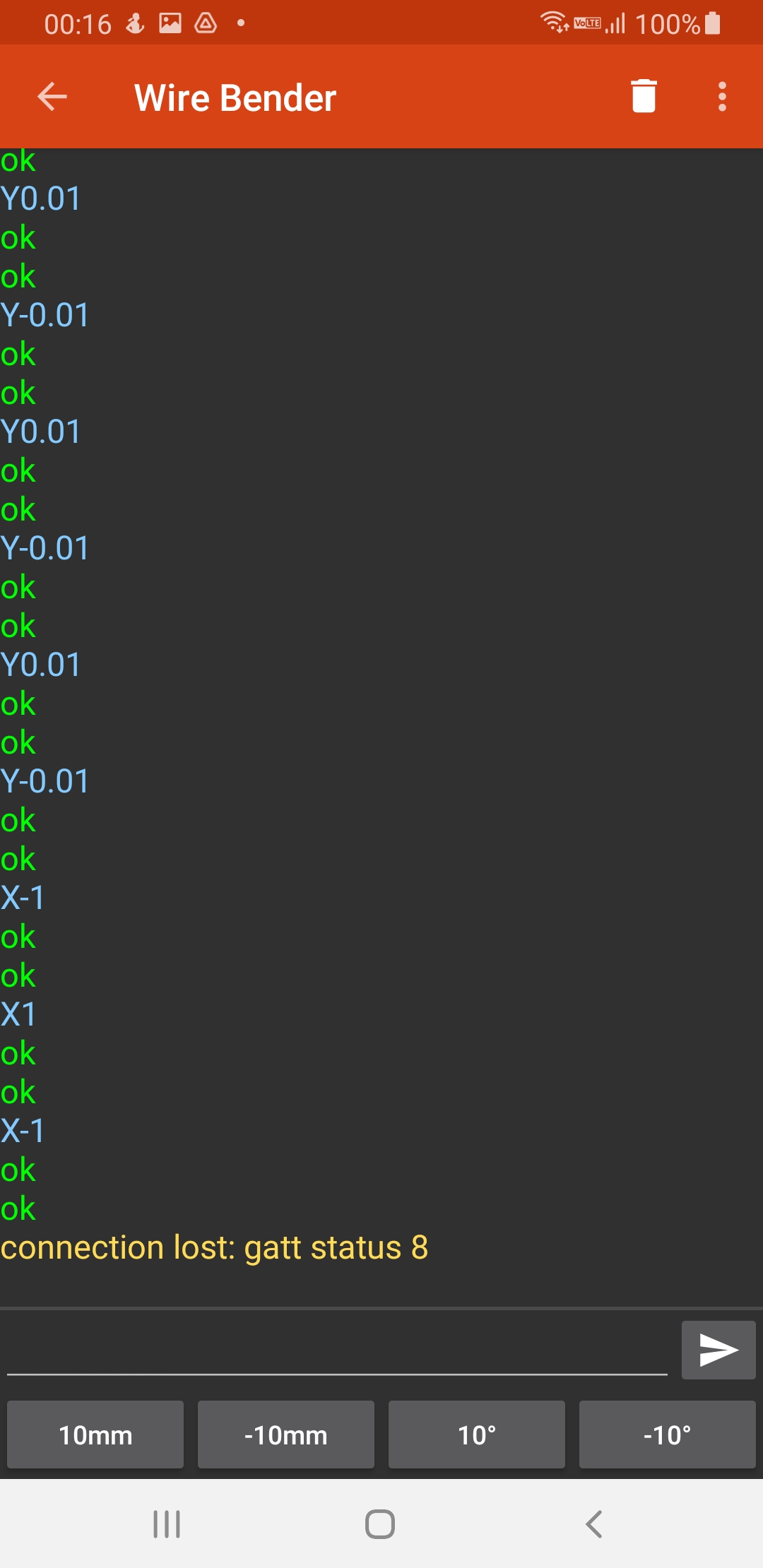
So I made this, a phone controlled wire bender. You plug it, establish a Bluetooth connection to it, and use the nifty android app I made to make it bend wire.

Details

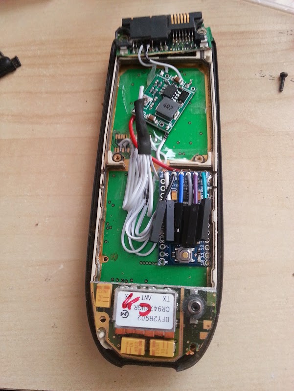
I had an idea that an 3d printer’s extruder could also be used to extrude wire. So mocked something up:

And then laser cut it.
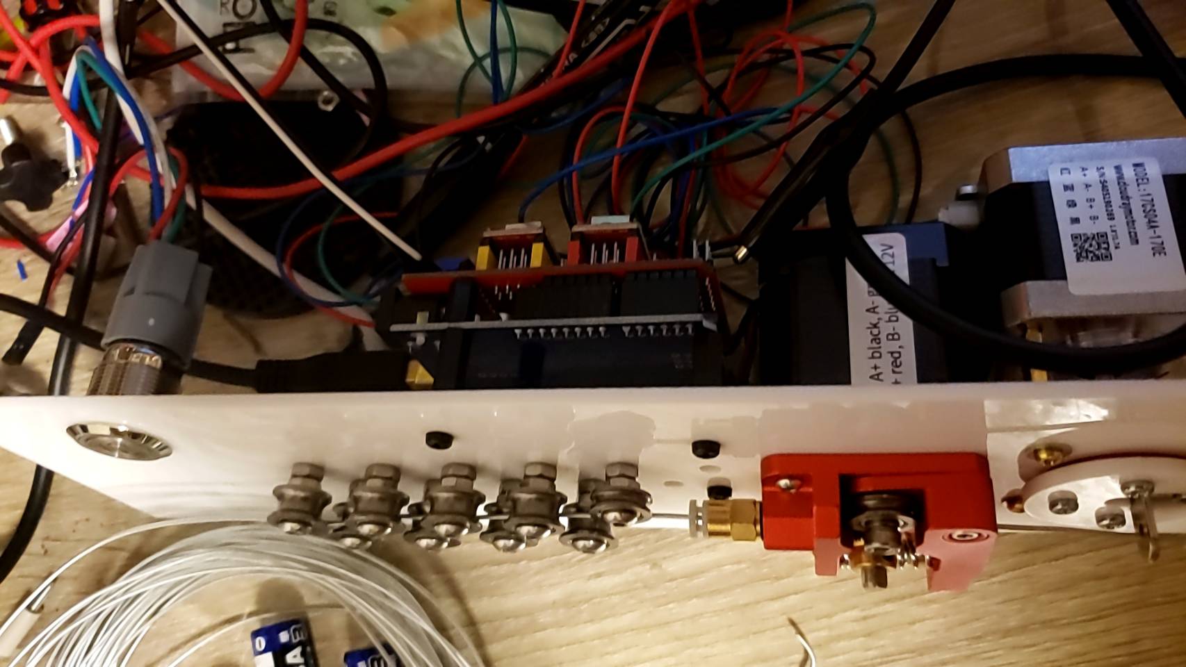
Mounting

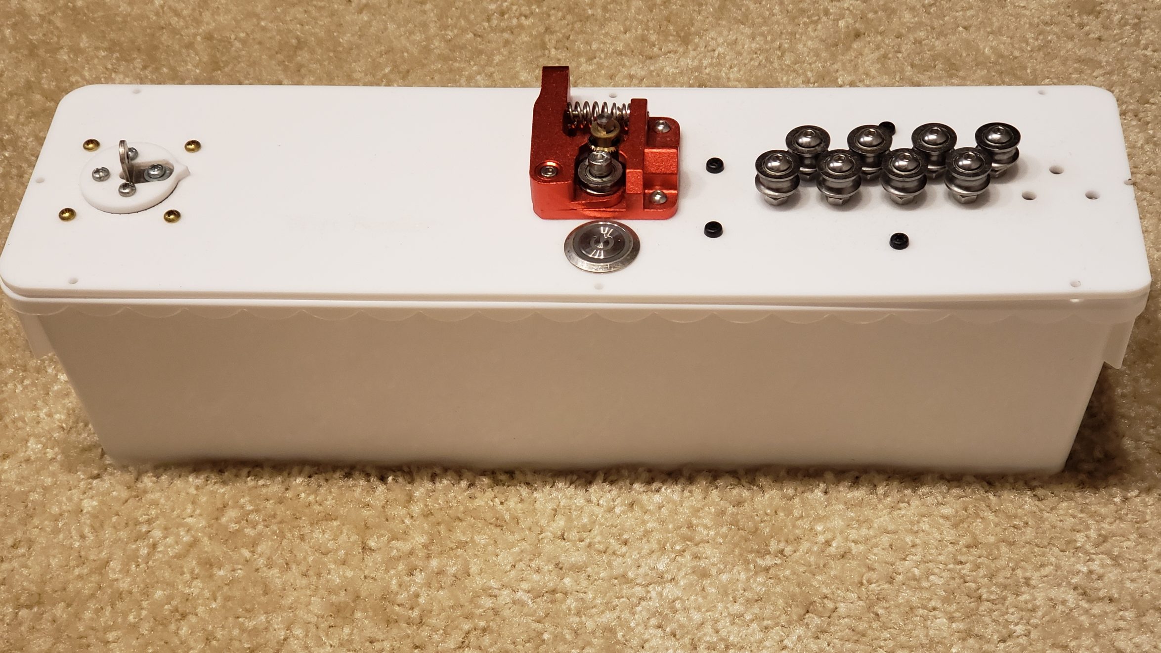
I decided to mount everything to top acrylic, except for the power connector.

Also, I didn’t do much wire management 🙂

The “project box” is actually a flower pot 🙂

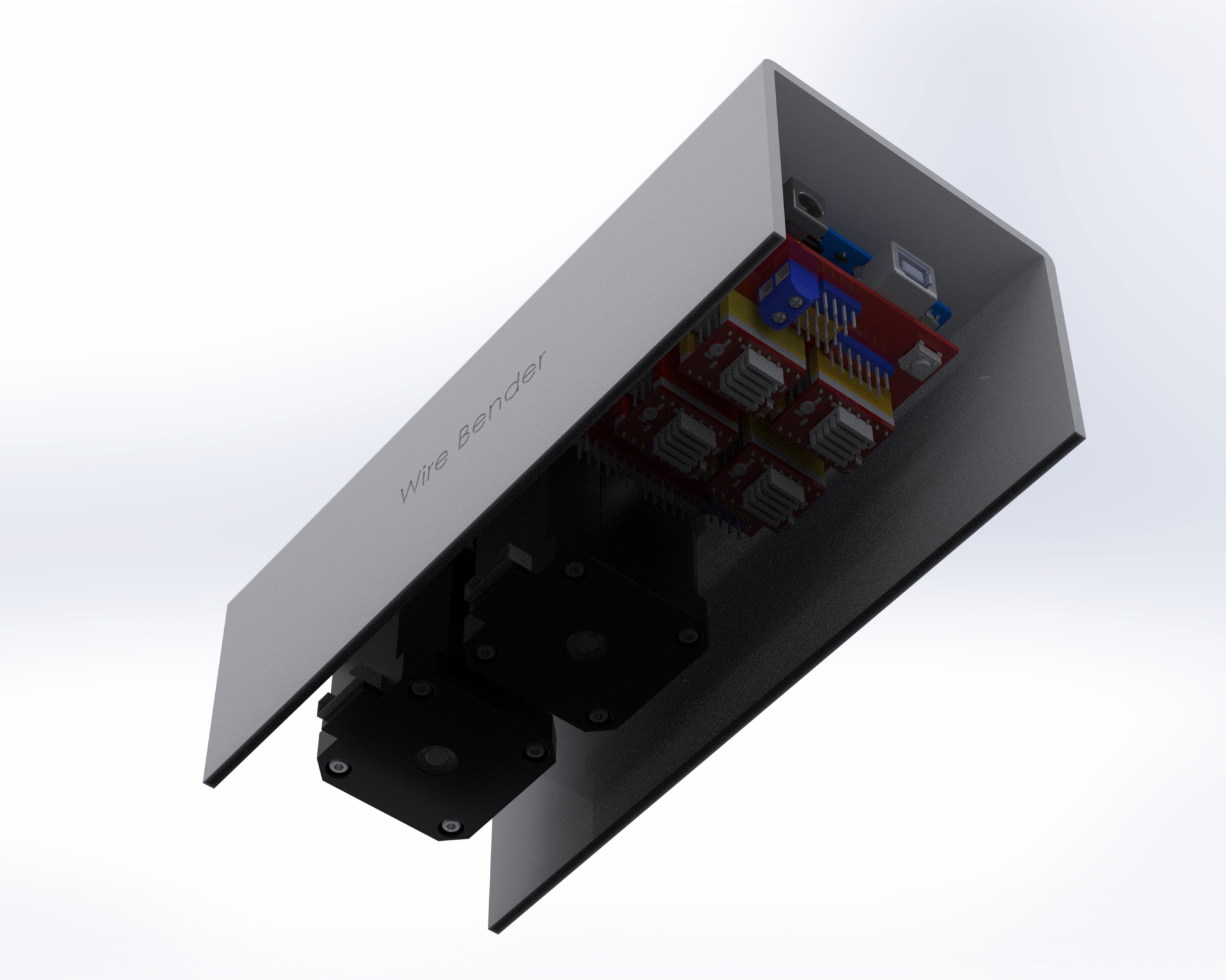
One thing I didn’t foresee with mounting everything upside down is that one of the heatsinks on the motor controller fell off. I had to add an acrylic plate on top to hold them in place. Also, I think I need some active cooling. I haven’t had any actual problems yet, despite bending a lot of wire, but I’m sure I’m doing the controllers and motors no favors.

Previous iterations

I actually went through quite a few iterations. Here was one of the first designs, before I realized that I needed the wire bending part to be much further away from the extruder:

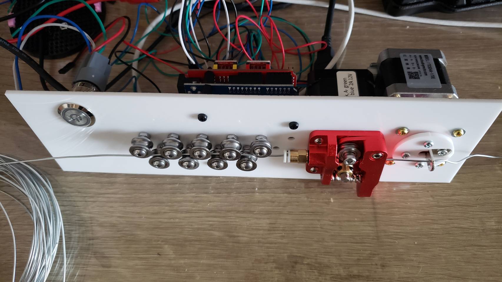
I went through a few different iterations. The set of 11 feeder ball-bearings are there to straighten the wire. It’s not obvious, but they actually converge at approximately a 2 degree angle, and I find this works best. So when the wire is initially fed in, the large spaced bearings smooth out the large kinks, and then the closer spaced bearings smooth out the small kinks. Try trying to do it all in one pass doesn’t work because the friction ends up being too high.

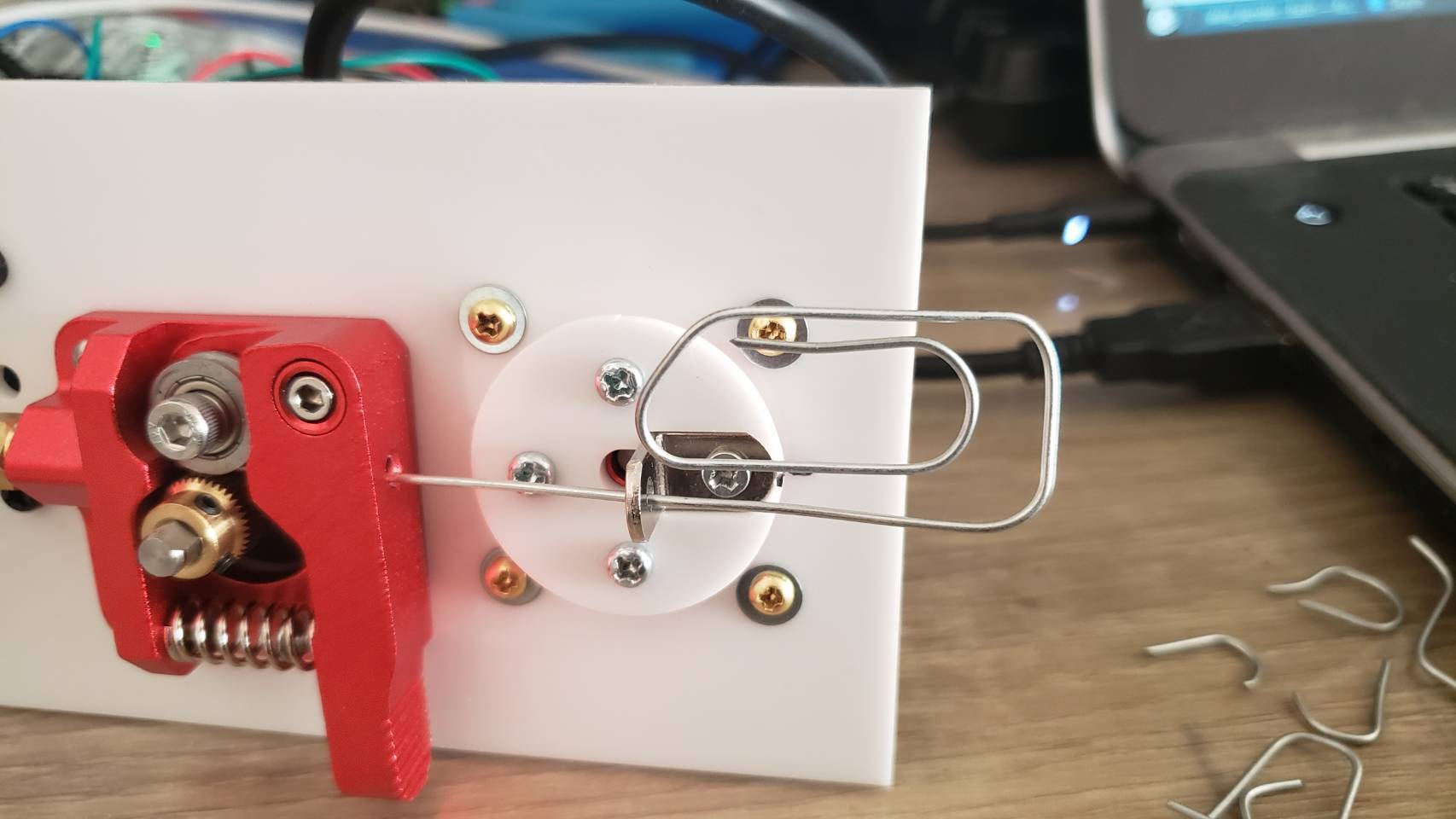
I replaced the extruder feeder with one with a much more ‘grippy’ surface. The grooved metal needs to be harder than the wire you’re feeding into it, so that it can grip it well. This did result in marks in the metal, but that was okay for my purpose. Using two feeder motors could help with this.

Algorithm

The algorithm to turn an arbitrary shape into a set of motor controls was actually pretty interesting, and a large part of the project. Because you have to bend the wire further than the angle you actually want, because it springs back. I plan to write this part up properly later.

Software control

For computer control, I connect the stepper motors to a stepper motor driver, which I connect to an Arduino, which communicates over bluetooth serial to an android app. For prototyping I actually connected it to my laptop, and wrote a program in python to control it.

Both programs were pretty basic, but the android app has a lot more code for UI, bluetooth communication etc. The python code is lot easier to understand:

#!/usr/bin/env python3

import serial
import time
from termcolor import colored
from typing import Union
try:
    import gnureadline as readline
except ImportError:
    import readline

readline.parse_and_bind('tab: complete')
baud=9600 # We override Arduino/libraries/grbl/config.h to change to 9600
# because that's the default of the bluetooth module

try:
    s = serial.Serial('/dev/ttyUSB0',baud)
    print("Connected to /dev/ttyUSB0")
except:
    s = serial.Serial('/dev/ttyUSB1',baud)
    print("Connected to /dev/ttyUSB1")

# Wake up grbl
s.write(b"\r\n\r\n")
time.sleep(2)   # Wait for grbl to initialize
s.flushInput()  # Flush startup text in serial input

def readLineFromSerial():
    grbl_out: bytes = s.readline() # Wait for grbl response with carriage return
    print(colored(grbl_out.strip().decode('latin1'), 'green'))

def readAtLeastOneLineFromSerial():
    readLineFromSerial()
    while (s.inWaiting() > 0):
        readLineFromSerial()

def runCommand(cmd: Union[str, bytes]):
    if isinstance(cmd, str):
        cmd = cmd.encode('latin1')
    cmd = cmd.strip() # Strip all EOL characters for consistency
    print('>', cmd.decode('latin1'))
    s.write(cmd + b'\n') # Send g-code block to grbl
    readAtLeastOneLineFromSerial()

motor_angle: float = 0.0
MICROSTEPS: int = 16
YSCALE: float = 1000.0

def sign(x: float):
    return 1 if x >= 0 else -1

def motorYDeltaAngleToValue(delta_angle: float):
    return delta_angle / YSCALE

def motorXLengthToValue(delta_x: float):
    return delta_x

def rotateMotorY_noFeed(new_angle: float):
    global motor_angle
    delta_angle = new_angle - motor_angle
    runCommand(f"G1 Y{motorYDeltaAngleToValue(delta_angle):.3f}")
    motor_angle = new_angle

def rotateMotorY_feed(new_angle: float):
    global motor_angle
    delta_angle = new_angle - motor_angle
    motor_angle = new_angle
    Y = motorYDeltaAngleToValue(delta_angle)

    wire_bend_angle = 30 # fixme
    bend_radius = 3
    wire_length_needed = 3.1415 * bend_radius * bend_radius * wire_bend_angle / 360
    X = motorXLengthToValue(wire_length_needed)
    runCommand(f"G1 X{X:.3f} Y{Y:.3f}")

def rotateMotorY(new_angle: float):
    print(colored(f'{motor_angle}°→{new_angle}°', 'cyan'))
    if new_angle == motor_angle:
        return

    if sign(new_angle) != sign(motor_angle):
        # We are switching from one side to the other side.
        if abs(motor_angle) > 45:
            # First step is to move to 45 on the initial side, feeding the wire
            rotateMotorY_feed(sign(motor_angle) * 45)
        if abs(new_angle) > 45:
            rotateMotorY_noFeed(sign(new_angle) * 45)
            rotateMotorY_feed(new_angle)
        else:
            rotateMotorY_noFeed(new_angle)
    else:
        if abs(motor_angle) < 45 and abs(new_angle) < 45:
            # both start and end are less than 45, so no feeding needed
            rotateMotorY_noFeed(new_angle)
        elif abs(motor_angle) < 45:
            rotateMotorY_noFeed(sign(motor_angle) * 45)
            rotateMotorY_feed(new_angle)
        elif abs(new_angle) < 45:
            rotateMotorY_feed(sign(motor_angle) * 45)
            rotateMotorY_noFeed(new_angle)
        else: # both new and old angle are >45, so feed
            rotateMotorY_feed(new_angle)

def feed(delta_x: float):
    X = motorXLengthToValue(delta_x)
    runCommand(f"G1 X{X:.3f}")

def zigzag():
    for i in range(3):
        rotateMotorY(130)
        rotateMotorY(60)
        feed(5)
        rotateMotorY(0)
        feed(5)
        rotateMotorY(-130)
        rotateMotorY(-60)
        feed(5)
        rotateMotorY(0)
        feed(5)

def s_shape():
    for i in range(6):
        rotateMotorY(120)
        rotateMotorY(45)
    rotateMotorY(-130)
    for i in range(6):
        rotateMotorY(-120)
        rotateMotorY(-45)
    rotateMotorY(0)
    feed(20)

def paperclip():
    rotateMotorY(120)
    feed(1)
    rotateMotorY(130)
    rotateMotorY(140)

    rotateMotorY(30)
    feed(3)
    rotateMotorY(140)
    rotateMotorY(45)
    feed(4)
    feed(10)
    rotateMotorY(140)
    rotateMotorY(45)
    feed(3)
    rotateMotorY(140)
    rotateMotorY(50)
    rotateMotorY(150)
    rotateMotorY(45)
    feed(5)
    rotateMotorY(0)

runCommand('F32000') # Feed rate - affects X and Y
runCommand('G91')
runCommand('G21')  # millimeters
runCommand(f'$100={6.4375 * MICROSTEPS}') # Number of steps per mm for X
runCommand(f'$101={YSCALE * 0.5555 * MICROSTEPS}') # Number of steps per YSCALE degrees for Y
runCommand('?')
#rotateMotorY(-90)
#paperclip()
while True:
    line = input('> ("stop" to quit): ').upper()
    if line == 'STOP':
        break
    if len(line) == 0:
        continue
    cmd = line[0]
    if cmd == 'R':
        val = int(line[1:])
        rotateMotorY(val)
    elif cmd == 'F':
        val = int(line[1:])
        feed(val)
    else:
        runCommand(line)

runCommand('G4P0') # Wait for pending commands to finish
runCommand('?')

s.close()

Advertisement

Health badge

Electronics

I bought a 128×128 SPI Nokia 5110 display (The ILI9163)  to hook up to an Arduino.  I used an Arduino Mini which runs at 3.3v, since the display uses 3.3v logic.

Then wired it up like:

- LED       -->     +3.3V  -  (5V would work too) 
- SCK       -->     Pin 13 -  Sclk,  (3.3V level)
- SDA       -->     Pin 11 -  Mosi,  (3.3V level)
- A0        -->     Pin 10 -  DC or RS pin (3.3V level)
- RST       -->     Pin 9  -  Or just connect to +3.3V
- CS        -->     Pin 8  -  CS pin (3.3V level)
- Gnd       -->     Gnd
- Vcc       -->     +3.3V

(Note that SDA and SCK pins aren’t optional, because we’re using the arduino SPI hardware to drive this. The DC and CS pins are changeable if you change the code)

layout1_bb

And found a library to use this:

cd /libraries/
git clone https://github.com/adafruit/Adafruit-GFX-Library
git clone https://github.com/sumotoy/TFT_ILI9163C

I had to then edit TFT_ILI9163C/TFT_ILI9163C.h to comment out the #define __144_RED_PCB__ , and uncomment the #define __144_BLACK_PCB__ since my PCB was black. Without this change I got corruption on the top 1/4 of the screen.

Now to get something up and running, using the above pin definition:

#include <SPI.h>
#include <Adafruit_GFX.h>
#include <TFT_ILI9163C.h>

/* SPI hardware runs on:
 MOSI:  11
 SCK:   13
 */
#define __CS 8
#define __DC 10
#define __RESET 9

TFT_ILI9163C tft = TFT_ILI9163C(__CS, __DC, __RESET);

const uint16_t WIDTH = 128;
const uint16_t HEIGHT = 128;

void setup(void) {
  tft.begin();
  tft.drawFastHLine(0, 0, WIDTH, 0xFFE0);
}

void loop() {
}

This now gives us a black sceen with a yellow line. Woohoo!

Now, I have a bunch of images that I got an artist to draw, that look like:

face10

I have 10 of these, and their raw size would be 128 * 128 * 4 * 10 = 655KB. Far too large for our 30KB of available flash memory on the nano!

But given the simplicity of the images, we can use a primitive compression algorithm and instead store these as Run Length Encoded. E.g. store as them as pixel index color followed by the number of pixels of that color in a line. We turn to trusty python to do this:

import os,sys
import itertools
from PIL import Image

rleBytes = 0
colorbits = 3

if len(sys.argv) != 3:
    print sys.argv[0], " <input file.png> <output file.h>"
    sys.exit()

def writeHeader(f):
    f.write("/* A generated file for a run length encoded image of " + sys.argv[1] + " */\n\n")
    f.write("#ifndef PIXEL_VALUE_TO_COLOR_INDEX\n")
    f.write("#define PIXEL_VALUE_TO_COLOR_INDEX(x) ((x) >> " + str(8-colorbits) + ")\n")
    f.write("#define PIXEL_VALUE_TO_RUN_LENGTH(x) ((x) & 0b" + ("1" *(8-colorbits)) + ")\n")
    f.write("#endif\n\n")
    f.write("namespace " + os.path.splitext(sys.argv[2])[0] + " {\n")
def writeFooter(f):
    f.write("}")

def writePalette(f, image):
    palette = image.im.getpalette()
    palette = map(ord, palette[:3*2**colorbits]) # This is now an array of bytes of the rgb565 values of the palette
    f.write("/* The RGB565 value for color 0 is in palette[0] and so on */\n")
    # convert from RGB888 to RGB565
    palette565 = [((palette[x] * 2**5 / 256) << 11) + ((palette[x+1] * 2**6 / 256) << 5) + ((palette[x+2] * 2**5/256)) for x in xrange(0, len(palette), 3)]
    f.write("const uint16_t palette[] PROGMEM = {" + ','.join(hex(x) for x in palette565) + "};\n\n")

def writePixel(pixelIndexColor, count):
    global rleBytes
    f.write(hex((pixelIndexColor << (8 - colorbits)) + count) + "," )
    rleBytes += 1

def writePixels(f):
    f.write("/* The first (MSB) " + str(colorbits) + "bits of each byte represent the color index, and the last " + str(8-colorbits) + " bits represent the number of pixels of that color */\n")
    f.write("const unsigned char pixels[] PROGMEM = {")
    (width, height) = image.size

    lastColors = []
    lastColor = -1
    lastColorCount = 0
    for y in xrange(height):
        for x in xrange(width):
            color = pix[x,y]
            if lastColorCount +1 < 2**(8 - colorbits) and (lastColorCount == 0 or color == lastColor):
                lastColorCount = lastColorCount + 1
            else:
                writePixel(lastColor, lastColorCount)
                lastColorCount = 1
            lastColor = color
        # To make the decoder easier, truncate at the end of a row
        # This adds about 5% to the total file size though
        writePixel(lastColor, lastColorCount)
        lastColorCount = 0
    f.write("};\n\n");


image = Image.open(sys.argv[1])
image = image.convert("P", palette=Image.ADAPTIVE, colors=2**colorbits)
#image.save("tmp.png")
pix = image.load()

f = open(sys.argv[2], 'w')
writeHeader(f)
writePalette(f, image)
writePixels(f)
writeFooter(f)
f.close()

print "Summary: Total Bytes: ", rleBytes

The result is that the 10 pictures take up 14kb. This doesn’t produce an optimal image, but it’s a decent starting point. This generates header files like:

/* A generated file for a run length encoded image of face1.png */

#ifndef PIXEL_VALUE_TO_COLOR_INDEX
#define PIXEL_VALUE_TO_COLOR_INDEX(x) ((x) >> 5)
#define PIXEL_VALUE_TO_RUN_LENGTH(x) ((x) & 0b11111)
#endif

namespace face1 {
/* The RGB565 value for color 0 is in palette[0] and so on */
const uint16_t palette[] PROGMEM = {0xef0b,0xf4a3,0x0,0xdb63,0xffff,0xa302,0xe54a,0x5181};

/* The first (MSB) 3 bits of each byte represent the color index, and the last 5 bits represent the number of pixels of that color */
const unsigned char pixels[] PROGMEM = {0x5f,0x56,0xe2...}
}

Which represents the image:

tmp

Which isn’t too bad for a first go. (This was generated by adding a image.save('tmp.png')" in the python code after converting the image).

Now we need an arduino sketch to pull this all in:

#include <SPI.h>
#include <Adafruit_GFX.h>
#include <TFT_ILI9163C.h>
#include "face1.h"
#include "face2.h"
#include "face3.h"
#include "face4.h"
#include "face5.h"
#include "face6.h"
#include "face7.h"
#include "face8.h"
#include "face9.h"
#include "face10.h"

const unsigned char *pixels[] = { face1::pixels, face2::pixels, face3::pixels, face4::pixels, face5::pixels, face6::pixels, face7::pixels, face8::pixels, face9::pixels, face10::pixels } ;
const unsigned char numpixels[] = { sizeof(face1::pixels), sizeof(face2::pixels), sizeof(face3::pixels), sizeof(face4::pixels), sizeof(face5::pixels), sizeof(face6::pixels), sizeof(face7::pixels), sizeof(face8::pixels), sizeof(face9::pixels), sizeof(face10::pixels) };
const uint16_t *palette[] = { face1::palette, face2::palette, face3::palette, face4::palette, face5::palette, face6::palette, face7::palette, face8::palette, face9::palette, face10::palette } ;


/*
 We are using 4 wire SPI here, so:
 MOSI:  11
 SCK:   13
 the rest of pin below:
 */
#define __CS 8
#define __DC 10
#define __RESET 9
TFT_ILI9163C tft = TFT_ILI9163C(__CS, __DC, __RESET);

const uint16_t width = 128;
const uint16_t height = 128;

void drawFace(int i);

void setup(void) {
  tft.begin();
}


void drawImage(const unsigned char *pixels, const unsigned char numPixels, const uint16_t *palette) {
  int16_t x = 0;
  int16_t y = 0;
  for( int i = 0; i < sizeof(face1::pixels); ++i) {
    unsigned char pixel = pgm_read_byte_near(pixels + i);
    /* The first (MSB) 3 of each byte represent the color index, and the last 5 bits represent the number of pixels of that color */
    unsigned char colorIndex = PIXEL_VALUE_TO_COLOR_INDEX(pixel);
    int16_t count = PIXEL_VALUE_TO_RUN_LENGTH(pixel);
    uint16_t color = pgm_read_word_near(palette + colorIndex);
    tft.drawFastHLine(x,y,count+1,color);
    x += count;
    if(x >= width) {
      x = 0;
      y+=1;
    }
  }
}

void loop() {
  for(int i = 1; i <= 10; ++i)
    drawFace(i);
}

void drawFace(int i) {
  drawImage(pixels[i-1], numpixels[i-1], palette[i-1]);
}

Pretty straight forward.

Using 4 bits per color uses up slightly too much space: 34,104 bytes (111%) of program storage.
Using 3 bits per color introduces slight artifcats, but presumably removable if we tweak the images, but it fits with plenty of room to space:

Sketch uses 20,796 bytes (67%) of program storage space. Maximum is 30,720 bytes.
Global variables use 134 bytes (6%) of dynamic memory, leaving 1,914 bytes for local variables. Maximum is 2,048 bytes.

The result is this:

Note that this is actually updating at maximum speed. There is room for improvement in the adafruit graphics code however, so I may have a go at improving this if I need faster updates. It might be nice to faster updates anyway in order to minimize battery use.

Android Phone App

I wanted to keep the Android app side of it as clean and simple as possible. There’s not much to document regarding the GUI side of things – it’s a pretty straightforward Android app.

The idea here is to connect via bluetooth to both the arduino and to a Healthband. It measures the heart rate and, more importantly, the very slightly changes in time between the heart pulses. By the knowing the users age, sex and weight, we can calculate the amount of stress that they are currently experiencing. We can then display that in the app, and send that information via Bluetooth Low Energy to our arduino heart badge.

Screenshot_2015-05-29-23-49-29

Screenshot_2015-05-29-23-51-15

It perhaps needs some tweaking – I’m not really that angry, honest!  Lots of polishing is still needed, but the barebones are starting to come together!

Nokia 6110 Part 1 – Electronics

Original Nokia 6110

This is a four part series:

The Nokia 6110 phone came with a snake game that was an instant success.  Many people bought the phone just to play the game.

I wanted to recreate this game, but have an AI playing it continually.

Final Result

This is the final result that I was aiming for:

Starting

I bought one of these phones from ebay, and took it apart.  It comprises of two boards – the top board controls the LCD and the buttons, and uses a ‘springy’ connector to connect to the bottom board.

Bottom Board

The bottom board contains all the phone electronics, including the power connector.

I don’t want to keep any of the phone electronics, so I took out my trusty saw and cut the middle part of the bottom board out, throwing it away and keeping the top most part and the bottom most part:

original_pcbCutting bottom boardPower Connector cut off

(Not shown here, but I also cut off the top part, purely for aesthetics, because the antenna pokes through the case).

Next, I soldered two wires to the power connector, using a multimeter to determine which wires to connect to.

Now that we have power, it’s time to move on to the top board, and get the LCD connected.

Top board

The LCD connects via a “zebra” connector to the board:

lcd

By finding and reading the PDF for this LCD display (pcd8544), we can work out which pins are which.  These pins map to the otherside of the board, connecting to the bottom board via the “springy connector” that I labelled in an image above.  Using a multimeter, I mapped out the pins.  The LED backlights are also helpfully connected here, via a transistor, so those were wired up too:

pin layout

The blue lines here indicate where I’ve shorted the connections to ground, and the red dotted lines is where I’ve shorted the connections to the power line.  In a future version I might leave the LED power separate, and power that separately, bypassing the arduino regulator.  The LEDs draw 100mA at 3.3V.

Here’s the final soldered product:

At this stage, I wrapped the board in salotape to provide a small amount of strength and to avoid any short circuits when placing other boards on top.

Arduino

In the first iteration of this, I used a 5V Arduino Nano running at 16Mhz, even though the display is supposed to accept only 3.3V logic and power.  I looked carefully at the display specifications, and it did appear that it should tolerate 5V.  However the result was that the display contrast was wrong.  So I switched to a 3.3V Arduino Pro Mini, running at 8 Mhz.

To make it possible to program the Arduino, I cut 6 female dupont leads and soldered them to the FTDI header.  This allows me to program the Arduino even when the phone is assembled.

Next I connected up the wires to the arduino pins as marked in the diagram (SCLK=pin2, SDIN=pin5, D/C=pin3, Res=pin4).  Optionally the backlight can be connected to pin6, but I hardwired it to power.

Regulator

In the first iteration of this, I then added an arduino and powered the arduino directly from the 7.9V input.  However the arduino’s has a linear regulator, meaning that it was producing (7.9V – 3.3V) * 100mA = 0.5 Watts of heat.  I thought that this would be tolerable, but it got a bit too warm for my liking inside the case.  So I added a switching regulator to convert 7.9V down to 3.6V, which I then fed to the arduino’s linear regulator.

Top half of the bottom board

Finally, I added the top half of the original board, simply so that the original antenna poked through.

Now the case can be screwed on, and we can start to program it by plugging in an FTDI usb connector:

Next up – Programming it!

3D Printer

On a whim, I decided to make a 3D printer.  I spent the weekend with my brother creating this, and I have to admit we did end up hacking it a lot.

The result wasn’t too bad:

I admit it’s very messy.

But on the first try, I had the temperature too high:

I did start work on an auto calibration system by just crafting a gcode file that would create triangles at various different settings, with a GUI program to let you say which one was best, and then automatically iterating on the best version.

But I got an offer from someone wanting to buy the reprap printer as-is, so I sold it.

I’m very excited to see how the future of 3D printing pans out.

Self Balancing Robot

This was my first electronics project – a simple self-balancing robot.

The wheels and chassis are from a toy truck.  Onto that I salotaped a breadboard with two Light-Dependant-Resistors, attached in series.  On one end I feed 5V, on the other end, ground.  This gives a voltage divider.  And in the middle I connect that to a resistor and a capacitor in parallel.  This gives me a Proportional Derivative signal (out of a PID controller).

This means that we can read off the current ratio of brightness that the two LDRs see, then add on to that signal the rate at which they are changing.  This helps prevent driving the motors too fast when we already moving rapidly towards the balancing point.

We then read this analog voltage on the Arduino, and use it to control the direction of the motors.

There is a huge amount of gear slop which is why it can only barely balance.