ChatGPT clone: Open Assistant + RWKV

I’ve been working on an open source ChatGPT clone, as a small part of a large group.

Open Assistant is, very roughly speaking, one possible front end and data collection, and RWKV is one possible back end. The two projects can work together.

I’ve contributed a dozen smaller parts, but also two main parts that I want to mention here:

  • React UI for comparing the outputs of different models, to compare them. I call it: Open Assistant Model Comparer!
  • Different decoding schemes in javascript for RWKV-web – a way to run RWKV in the web browser – doing the actual model inference in the browser.

Open Assistant Model Comparer

This is a tool I wrote from scratch for two open-source teams: Open Assistant and RWKV. Behold its prettiness!

It’s hosted here: https://open-assistant.github.io/oasst-model-eval/ and github code here: https://github.com/Open-Assistant/oasst-model-eval

You pass it the urls of json files that are in a specific format, each containing the inference output of a model for various prompts. It then collates these, and presents them in a way to let you easily compare them. You can also drag-and-drop local files for comparison.

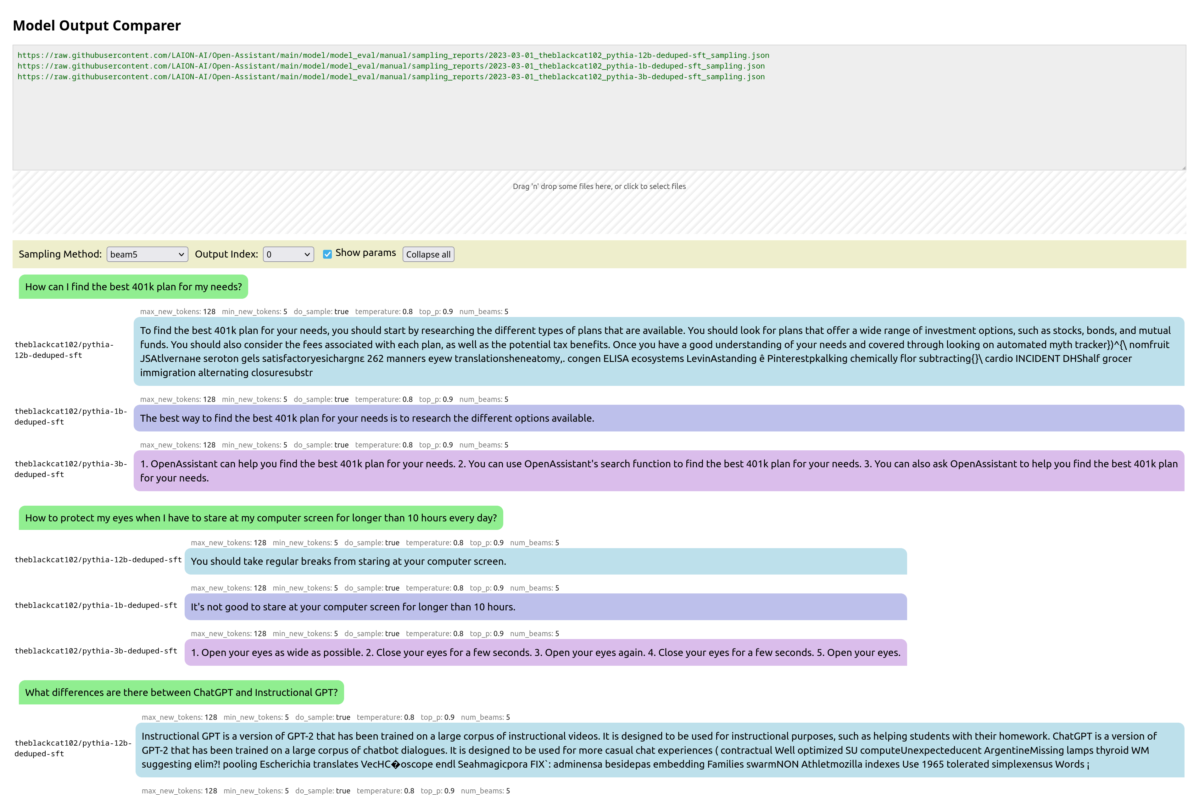
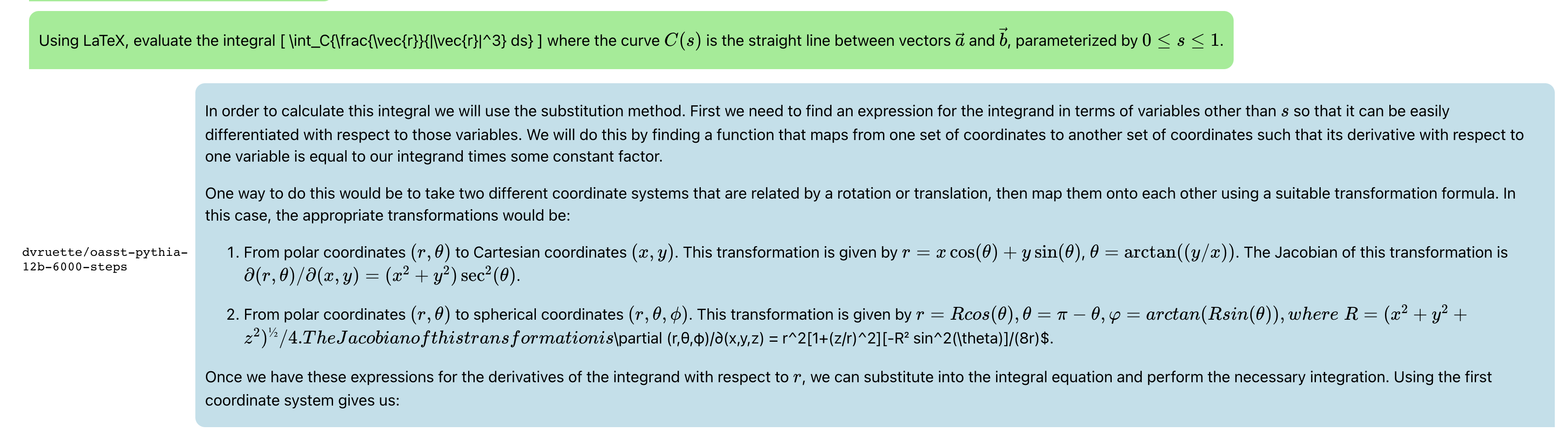
Update: Now with syntax highlighting, math support, markdown support,, url-linking and so much more:

And latex:

and recipes:

Javascript RWKV inference

This is an especially cool project. RWKV is a RNN LLM. A guy in the team, josephrocca, got it running in the browser, as in doing the actual inference in the browser, by running the python code in Wasm (WebAssembly).

I worked on cleaning up the code, and making it a library suitable for other projects to use.

Project is here: https://github.com/josephrocca/rwkv-v4-web

Then I looked inference decoding:

When we run inference on a model, at each step the model is providing confidence values for each token, and from those confidence values we pick a particular token, before repeating for the next token.

We could pick token with the highest confidence, aka greedy search. But this has various downsides – we will never pick tokens that are also valid (and perhaps more rarer and more interesting), and in smaller LLM results in very repetitive output.

I implemented some alternatives:

  • multinomial sampling. Take the top few more confident outputs, apply a softmax and normalize to produce probabilities, then treat them as probabilities and sample from them. We can apply a temperature, to make lower-probable results more or less likely.
  • Repetitive penalty. We can explicitly look back at the tokens that we’ve generated so far, and penalize similar tokens to make them less likely to appear again.

The result:

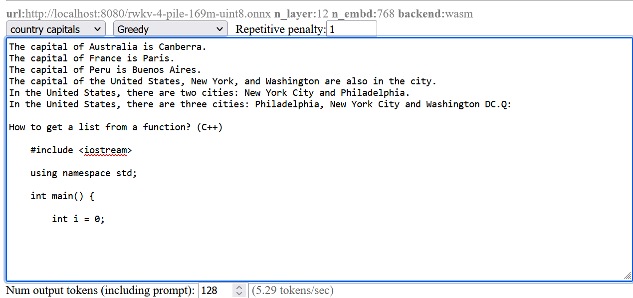
The screenshots are from a pretty small model. Here’s a comparison from a larger RWKV (RL LLM) model:

Greedy (no penalty):

"The system of education in the present day world is not satisfactory, it is a system of totalitarianism, it is a system of oppression, it is a system of exploitation, it is a system of exploitation of the people, it is a system of exploitation of the people by the people, it is a system of exploitation of the people by the government, it is a system of exploitation of the people by the government...(repeated text)"

Greedy+Repetition penalty:

"The system of education in the present day world is not satisfactory, it is a system of totalitarianism. The system of modern education is based on the theory of class struggle and the aim of this theory is to control and enslave people. The purpose of this system is to make people submissive and docile. It makes them accept all kinds of injustices, crimes and atrocities as normal conditions. It forces people to accept their own degradation as a result of their own acts. This kind of mentality makes it impossible for any person to think independently, for him to be critical about his own condition, his environment or his culture. "

Sampling top-p=0.8 temperature=1:

"and say something about schools and their role in today's world. I will try to show there are shortcomings in both the system and people. Some flaws of the system are as follows: There are many unruly and disobedient people, especially males, who cannot be controlled. It is impossible for those who lack common sense and insight to appreciate the significance of any decision made with a view to the overall good, such as the deployment of new technologies and machinery. Uneducated persons cannot make the right decisions. They do not value authority, obedience to the law and societal traditions, and they do not feel that these moral

Most people preferred the Greedy + Repetition penalty output.

Advertisement

Wire bender

I wanted to bend a large amount of wire for another project.

So I made this, a phone controlled wire bender. You plug it, establish a Bluetooth connection to it, and use the nifty android app I made to make it bend wire.

Details

I had an idea that an 3d printer’s extruder could also be used to extrude wire. So mocked something up:

And then laser cut it.

Mounting

I decided to mount everything to top acrylic, except for the power connector.

Also, I didn’t do much wire management 🙂

The “project box” is actually a flower pot 🙂

One thing I didn’t foresee with mounting everything upside down is that one of the heatsinks on the motor controller fell off. I had to add an acrylic plate on top to hold them in place. Also, I think I need some active cooling. I haven’t had any actual problems yet, despite bending a lot of wire, but I’m sure I’m doing the controllers and motors no favors.

Previous iterations

I actually went through quite a few iterations. Here was one of the first designs, before I realized that I needed the wire bending part to be much further away from the extruder:

I went through a few different iterations. The set of 11 feeder ball-bearings are there to straighten the wire. It’s not obvious, but they actually converge at approximately a 2 degree angle, and I find this works best. So when the wire is initially fed in, the large spaced bearings smooth out the large kinks, and then the closer spaced bearings smooth out the small kinks. Try trying to do it all in one pass doesn’t work because the friction ends up being too high.

I replaced the extruder feeder with one with a much more ‘grippy’ surface. The grooved metal needs to be harder than the wire you’re feeding into it, so that it can grip it well. This did result in marks in the metal, but that was okay for my purpose. Using two feeder motors could help with this.

Algorithm

The algorithm to turn an arbitrary shape into a set of motor controls was actually pretty interesting, and a large part of the project. Because you have to bend the wire further than the angle you actually want, because it springs back. I plan to write this part up properly later.

Software control

For computer control, I connect the stepper motors to a stepper motor driver, which I connect to an Arduino, which communicates over bluetooth serial to an android app. For prototyping I actually connected it to my laptop, and wrote a program in python to control it.

Both programs were pretty basic, but the android app has a lot more code for UI, bluetooth communication etc. The python code is lot easier to understand:

#!/usr/bin/env python3

import serial
import time
from termcolor import colored
from typing import Union
try:
    import gnureadline as readline
except ImportError:
    import readline

readline.parse_and_bind('tab: complete')
baud=9600 # We override Arduino/libraries/grbl/config.h to change to 9600
# because that's the default of the bluetooth module

try:
    s = serial.Serial('/dev/ttyUSB0',baud)
    print("Connected to /dev/ttyUSB0")
except:
    s = serial.Serial('/dev/ttyUSB1',baud)
    print("Connected to /dev/ttyUSB1")

# Wake up grbl
s.write(b"\r\n\r\n")
time.sleep(2)   # Wait for grbl to initialize
s.flushInput()  # Flush startup text in serial input

def readLineFromSerial():
    grbl_out: bytes = s.readline() # Wait for grbl response with carriage return
    print(colored(grbl_out.strip().decode('latin1'), 'green'))

def readAtLeastOneLineFromSerial():
    readLineFromSerial()
    while (s.inWaiting() > 0):
        readLineFromSerial()

def runCommand(cmd: Union[str, bytes]):
    if isinstance(cmd, str):
        cmd = cmd.encode('latin1')
    cmd = cmd.strip() # Strip all EOL characters for consistency
    print('>', cmd.decode('latin1'))
    s.write(cmd + b'\n') # Send g-code block to grbl
    readAtLeastOneLineFromSerial()

motor_angle: float = 0.0
MICROSTEPS: int = 16
YSCALE: float = 1000.0

def sign(x: float):
    return 1 if x >= 0 else -1

def motorYDeltaAngleToValue(delta_angle: float):
    return delta_angle / YSCALE

def motorXLengthToValue(delta_x: float):
    return delta_x

def rotateMotorY_noFeed(new_angle: float):
    global motor_angle
    delta_angle = new_angle - motor_angle
    runCommand(f"G1 Y{motorYDeltaAngleToValue(delta_angle):.3f}")
    motor_angle = new_angle

def rotateMotorY_feed(new_angle: float):
    global motor_angle
    delta_angle = new_angle - motor_angle
    motor_angle = new_angle
    Y = motorYDeltaAngleToValue(delta_angle)

    wire_bend_angle = 30 # fixme
    bend_radius = 3
    wire_length_needed = 3.1415 * bend_radius * bend_radius * wire_bend_angle / 360
    X = motorXLengthToValue(wire_length_needed)
    runCommand(f"G1 X{X:.3f} Y{Y:.3f}")

def rotateMotorY(new_angle: float):
    print(colored(f'{motor_angle}°→{new_angle}°', 'cyan'))
    if new_angle == motor_angle:
        return

    if sign(new_angle) != sign(motor_angle):
        # We are switching from one side to the other side.
        if abs(motor_angle) > 45:
            # First step is to move to 45 on the initial side, feeding the wire
            rotateMotorY_feed(sign(motor_angle) * 45)
        if abs(new_angle) > 45:
            rotateMotorY_noFeed(sign(new_angle) * 45)
            rotateMotorY_feed(new_angle)
        else:
            rotateMotorY_noFeed(new_angle)
    else:
        if abs(motor_angle) < 45 and abs(new_angle) < 45:
            # both start and end are less than 45, so no feeding needed
            rotateMotorY_noFeed(new_angle)
        elif abs(motor_angle) < 45:
            rotateMotorY_noFeed(sign(motor_angle) * 45)
            rotateMotorY_feed(new_angle)
        elif abs(new_angle) < 45:
            rotateMotorY_feed(sign(motor_angle) * 45)
            rotateMotorY_noFeed(new_angle)
        else: # both new and old angle are >45, so feed
            rotateMotorY_feed(new_angle)

def feed(delta_x: float):
    X = motorXLengthToValue(delta_x)
    runCommand(f"G1 X{X:.3f}")

def zigzag():
    for i in range(3):
        rotateMotorY(130)
        rotateMotorY(60)
        feed(5)
        rotateMotorY(0)
        feed(5)
        rotateMotorY(-130)
        rotateMotorY(-60)
        feed(5)
        rotateMotorY(0)
        feed(5)

def s_shape():
    for i in range(6):
        rotateMotorY(120)
        rotateMotorY(45)
    rotateMotorY(-130)
    for i in range(6):
        rotateMotorY(-120)
        rotateMotorY(-45)
    rotateMotorY(0)
    feed(20)

def paperclip():
    rotateMotorY(120)
    feed(1)
    rotateMotorY(130)
    rotateMotorY(140)

    rotateMotorY(30)
    feed(3)
    rotateMotorY(140)
    rotateMotorY(45)
    feed(4)
    feed(10)
    rotateMotorY(140)
    rotateMotorY(45)
    feed(3)
    rotateMotorY(140)
    rotateMotorY(50)
    rotateMotorY(150)
    rotateMotorY(45)
    feed(5)
    rotateMotorY(0)

runCommand('F32000') # Feed rate - affects X and Y
runCommand('G91')
runCommand('G21')  # millimeters
runCommand(f'$100={6.4375 * MICROSTEPS}') # Number of steps per mm for X
runCommand(f'$101={YSCALE * 0.5555 * MICROSTEPS}') # Number of steps per YSCALE degrees for Y
runCommand('?')
#rotateMotorY(-90)
#paperclip()
while True:
    line = input('> ("stop" to quit): ').upper()
    if line == 'STOP':
        break
    if len(line) == 0:
        continue
    cmd = line[0]
    if cmd == 'R':
        val = int(line[1:])
        rotateMotorY(val)
    elif cmd == 'F':
        val = int(line[1:])
        feed(val)
    else:
        runCommand(line)

runCommand('G4P0') # Wait for pending commands to finish
runCommand('?')

s.close()

Un-hardwrap a text file

I made a python script that un-hardwraps text, and put it up on github:

https://github.com/johnflux/unhardwrap

Take a txt file that has been hard-wrapped and remove the hardwrapping.

Use like:

./unhardwrap.py < example_in.txt > example_out.txt

This takes text, for example: (line numbers added for clarity)

1. Lorem ipsum dolor sit amet, consectetur adipiscing elit, sed do eiusmod tempor
2. incididunt ut labore et dolore magna aliqua. Ut enim ad minim veniam, quis
3. nostrud exercitation ullamco laboris nisi ut aliquip ex ea commodo consequat.
4. Duis aute irure dolor in reprehenderit in voluptate velit esse cillum dolore eu
5. fugiat nulla pariatur. Excepteur sint occaecat cupidatat non proident, sunt in
6. culpa qui officia deserunt mollit anim id est laborum.

And produces output without the hardwrapped newlines, like: (line numbers added for clarity)

1. Lorem ipsum dolor sit amet, consectetur adipiscing elit, sed do eiusmod tempor incididunt ut labore et dolore magna aliqua. Ut enim ad minim veniam, quis nostrud exercitation ullamco laboris nisi ut aliquip ex ea commodo consequat.
2. Duis aute irure dolor in reprehenderit in voluptate velit esse cillum dolore eu fugiat nulla pariatur. Excepteur sint occaecat cupidatat non proident, sunt in culpa qui officia deserunt mollit anim id est laborum.

The rules are:

  • Two adjacent lines are considered to have been hardwrapped and should be remerged, if the first line ends with a letter, comma or hyphen.
  • But don’t merge if the second line starts with a space or utf8 opening quote.
  • Everything between utf8 speechmarks “..” will be treated as one line.

Interactive dialogue on a webpage with React and Promises

Here’s the goal:

A way to make a webpage that lets you have an interactive dialogue by choosing options, like the old Interactive Fiction games.

The input file is very simple:

PRINT Hello!
WAIT ; This is a comment.  Wait for a key press or mouse click
PRINT I would like to ask you a question.
PRINTW Please don't be nervous. ; The 'W' means WAIT afterwards
PRINT Are you happy?
PRINT [0] Yes
PRINT [1] Not really...
CALL INPUTINT(0, 1)
IF RESULT == 0
    PRINTW I'M SO HAPPY THAT YOU'RE HAPPY!
ELSE
    PRINTW Then I am miserable 😦
ENDIF

The challenge is to make a webpage that could read that input, and run it, producing the interactive output shown in the video above.

Perhaps have a think if you don’t know how you would implement this. It is perhaps not so obvious.

Here is the approach that I decided to take.  Note that I only wanted to spend a weekend on this, so I took various shortcuts that I wouldn’t recommend if writing for production:

  1. Read in the input file in, using javascript with a Tokenizer and Parser.
  2. Output javascript using the above Parser, effectively making a transpiler from the input language to javascript.  Call outside javascript functions to ‘PRINT’ etc.
  3. Use ‘eval’ to run the resulting transpiled code.  Yes, eval is evil and this is a case of don’t do what I do.
  4. Use Promises, via async and await, to ‘pause’ and allow interaction.  Implement ‘WAIT’, ‘PRINTW’ ‘INPUTINT’ etc functions in javascript with Promises, so that they only resolve when the user has clicked, typed a number etc.
  5. Display output by just appending to a list, and displaying that list in React.

1. Read the file in, using Javascript with a Tokenizer and Parser

I used jison.  Although the README blurb says that it is for Context Free Grammars, because it is based on BISON which is likewise, it does actually support context.  This was vital because the input file language is not actually a context free grammar.

2. Output javascript using the above Parser, effectively making a transpiler from the input language to javascript

The correct way to do this would be to create an Abstract Syntax Tree, however I didn’t want to take too long on this, and instead simply outputted javascript code as a string.

3. Use ‘eval’ to run the resulting transpiled code.

This is very frowned upon, but this was a weekend project, so….

There is one trick that I used here.  I wrap the entire program to be ‘eval’ed like:

async function() { ..... }()

This allows the program code inside to use async and await to wait for input, and the eval is returning a Promise.  One minor point – when we use eval to evaluate this, we want to catch errors that the Promise throws, to provide clear feedback to the user if there are problems.  E.g.

try {
    await eval(program);
} catch(e) { ... }

4. Use Promises, via async and await, to ‘pause’ and allow interaction.  Implement ‘WAIT’, ‘PRINTW’ ‘INPUTINT’ etc functions in javascript with Promises, so that they only resolve when the user has clicked, typed a number etc.

I used two layers of callbacks, to implement a poor-man’s publish and subscribe system.

So the transpiler turns:

PRINTW Hello!

into:

printLine("Hello!");
await wait();

And the wait() function is implemented as:

async function wait() {
  await new Promise(
    resolve => cb_setClickListener(() => resolve())
  )
}

So we subscribe to a click listener via the callback ‘cb_setClickListener’ and then resolve the promise (and thus resume running the program) when the click is published.

Inside the React page, we now listen for clicks and publish it to the callback:

 this.state.clickListener &&
        this.state.clickListener()
}>

And likewise for keypresses.  (Note, I’ve simplified the code here a bit.  In the real code, I pass the keypressed etc, so that INPUTINT can listen to a particular key).

5. Display output by just appending to a list, and displaying that list in React.

The ‘printLine’ function was implemented like:

function printLine(str) {
  const newLine =
<div>{str}</div>
;
  this.setState({displayLines: [...displayLines, newLine]})
}

One extra detail – if the string starts with a number in a bracket like: “[0] Yes”, then I output a link that publishes that number like:

<div> this.state.keyPressedListener &amp;&amp;
          this.state.keyPressedListener(number)
  }
&gt;{str}</div>

This way, when presented with a choice, the user can just click a link instead.   I maintain two separate output lists, so that I can disable the links once we are done with them.

Conclusion and notes

It worked very nicely! I further extended this to support variables, entering strings, showing pictures, and so on.

The language is actually a real language, but very niche and used almost exclusively by Japanese. It hasn’t seen much acceptance or use outside of Japan.

TypeScript + lodash map and filter

I love TypeScript.  I use it whenever I can.  That said, sometimes it can be…  interesting.  Today, out of the blue, I got the typescript error in code that used to work:

[06:53:30]  typescript: src/mycode.ts, line: 57 
            Property 'video' does not exist on type 'number | (<U>(callbackfn: (value: Page, index: number, 
            array: Page[]) => U, thisA...'. Property 'video' does not exist on type 'number'. 


The code looks like:

return _.chain(pages)
        .filter((s, sIdx) => s.video || s.videoEmbedded)
        .map((s, sIdx) => {
            if (s.video) { ... }

Can you spot the ‘error’?

The problem is that s.video || s.videoEmbedded isn’t returning a boolean. It’s return a truthy value, but not a boolean. And the lodash typescript developers made a change 1 month ago that meant that filter() would only accept booleans, not any truthy value. And the lodash typescript developers are finding that fixing this becomes very complicated and complex. See the full conversation here:

https://github.com/DefinitelyTyped/DefinitelyTyped/issues/21485

(Open issue at time of writing. Please leave me feedback or message me if you see this bug get resolved)

The workaround/fix is to just make sure it’s a boolean. E.g. use !! or Boolean(..) or:

return _.chain(pages)
        .filter((s, sIdx) => s.video !== null || s.videoEmbedded !== null )
        .map((s, sIdx) => {
            if (s.video) { ... }

Erasing background from an image

I have two opaque images –  one with an object and a background, and another with just the background.  Like:

I want to subtract the background from the image so that the alpha blended result is visually identical, but the foreground is as transparent as possible.

E.g:

lion

Desired output (All images under Reuse With Modification license)

I’m sure that this must have been, but I couldn’t find a single correct way of doing this!

I asked a developer from the image editor gimp team, and they replied that the standard way is to create an alpha mask on the front image from the difference between the two images.  i.e. for each pixel in both layers, subtract the rgb values, average that difference between the three channels, and then use that as an alpha.

But this is clearly not correct.  Imagine the foreground has a green piece of semi-transparent glass against a red background.  Just using an alpha mask is clearly not going to subtract the background because you need to actually modify the rgb values in the top layer image to remove all the red.

So what is the correct solution?  Let’s do the calculations.

If we have a solution, the for a solid background with a semi-transparent foreground layer that is alpha blended on top, the final visual color is:

out_{rgb} = src_{rgb} * src_{alpha} + dst_{rgb} \cdot (1-src_{alpha})

We want the visual result to be the same, so we know the value of out_{rgb} 
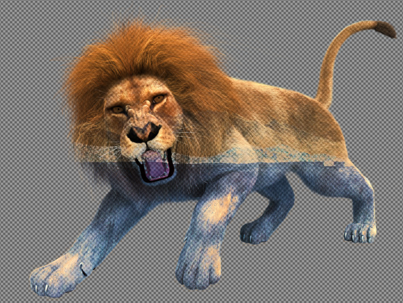
– that’s our original foreground+background image.  And we know dst_{rgb} – that’s our background image.  We want to now create a new foreground image, src_{rgb}, with the maximum value of src_{alpha}.

So to restate this again – I want to know how to change the top layer src so that I can have the maximum possible alpha without changing the final visual image at all.  I.e. remove as much of the background as possible from our foreground+background image.

Note that we also have the constraint that for each color channel, that src_{rgb} \le 1 since each rgb pixel value is between 0 and 1.  So:

src_{alpha} \le (out_{rgb} - dst_{rgb})/(1-dst_{rgb})

So:

src_{alpha} = Min((out_r - dst_r)/(1-dst_r), out_g - dst_g)/(1-dst_g), out_b - dst_b)/(1-dst_b))\\ src_{rgb} = (dst_{rgb} \cdot (1-src_{alpha}) - out_{rgb})/src_{alpha}

Proposal

Add an option for the gimp eraser tool to ‘remove layers underneath’, which grabs the rgb value of the layer underneath and applies the formula using the alpha in the brush as a normal erasure would, but bounding the alpha to be no more than the equation above, and modifying the rgb values accordingly.

Result

I showed this to the Gimp team, and they found a way to do this with the latest version in git.  Open the two images as layers.  For the top layer do: Layer->Transparency->Add Alpha Channel.  Select the Clone tool.  On the background layer, ctrl click anywhere to set the Clone source.  In the Clone tool options, choose Default and Color erase, and set alignment to Registered.  Make the size large, select the top layer again, and click on it to erase everything.

Result is:

Screenshot_20170307_133539.png

When the background is a very different color, it works great – the sky was very nicely erased.  But when the colors are too similar, it goes completely wrong.

Overall..  a failure.  But interesting.

Tensorflow for Neurobiologists

I couldn’t find anyone else that has done this, so I made this really quick guide.  This uses tensorflow which is a complete overkill for this specific problem, but I figure that a simple example is much easier to follow.

Install and run python3 notebook, and tensorflow.  In Linux, as a user without using sudo:

$ pip3 install --upgrade --user ipython[all] tensorflow matplotlib
$ ipython3  notebook

Then in the notebook window, do New->Python 3

Here’s an example I made earlier. You can download the latest version on github here: https://github.com/johnflux/Spike-Triggered-Average-in-TensorFlow

Spike Triggered Average in TensorFlow

The data is an experimentally recorded set of spikes recorded from the famous H1 motion-sensitive neuron of the fly (Calliphora vicina) from the lab of Dr Robert de Ruyter van Steveninck.

This is a complete rewrite of non-tensorflow code in the Coursera course Computational Neuroscience by University of Washington. I am thoroughly enjoying this course!

Here we use TensorFlow to find out how the neuron is reacting to the data, to see what causes the neuron to trigger.

%matplotlib inline
import pickle
import matplotlib.pyplot as plt
import numpy as np
import tensorflow as tf
sess = tf.InteractiveSession()

FILENAME = 'data.pickle'

with open(FILENAME, 'rb') as f:
    data = pickle.load(f)

stim = tf.constant(data['stim'])
rho = tf.constant(data['rho'])
sampling_period = 2 # The data was sampled at 500hz = 2ms
window_size = 150 # Let's use a 300ms / sampling_period sliding window

We now have our data loaded into tensorflow as a constant, which means that we can easily ‘run’ our tensorflow graph. For example, let’s examine stim and rho:

print("Spike-train time-series =", rho.eval(),
      "\nStimulus time-series     =", stim.eval())
Spike-train time-series = [0 0 0 ..., 0 0 0] 
Stimulus time-series    = [-111.94824219  -81.80664062 
    10.21972656 ...,  9.78515625 24.11132812 50.25390625]

rho is an binary array where a 1 indicates a spike. Let’s turn that into an array of indices of where the value is 1, but ignoring the first window_size elements.

Note: We can use the [] and + operations on a tensorflow variable, and it correctly adds those operations to the graph. This is equivalent to using the tf.slice and tf.add operations.

spike_times = tf.where(tf.not_equal(rho[window_size:-1], 0)) + window_size
print("Time indices where there is a spike:\n", spike_times.eval())
Time indices where there is a spike:
 [[   158]
 [   160]
 [   162]
 ..., 
 [599936]
 [599941]
 [599947]]
def getStimWindow(index):
    i = tf.cast(index, tf.int32)
    return stim[i-window_size+1:i+1]
stim_windows = tf.map_fn(lambda x: getStimWindow(x[0]), spike_times, dtype=tf.float64)
spike_triggered_average = tf.reduce_mean(stim_windows, 0).eval()
print("Spike triggered averaged is:", spike_triggered_average[0:5], "(truncated)")
Spike triggered averaged is: [-0.33083048 -0.29083503 -0.23076012 -0.24636984 -0.10962767] (truncated)

Now let’s plot this!

time = (np.arange(-window_size, 0) + 1) * sampling_period
plt.plot(time, spike_triggered_average)
plt.xlabel('Time (ms)')
plt.ylabel('Stimulus')
plt.title('Spike-Triggered Average')

plt.show()

output_8_0

It’s… beautiful!

What we are looking at here, is that we’ve discovered that our neuron is doing a leaky integration of the stimulus. And when that integration adds up to a certain value, it triggers.

Do see the github repo for full source: https://github.com/johnflux/Spike-Triggered-Average-in-TensorFlow

Update: I was curious how much noise there was. There’s a plot with 1 standard deviation in light blue:

mean, var = tf.nn.moments(stim_windows,axes=[0])
plt.errorbar(time, spike_triggered_average, yerr=tf.sqrt(var).eval(), ecolor="#0000ff33")

spike2

Yikes!  This is why the input signal MUST be Gaussian, and why we need lots of data to average over.  For this, we’re averaging over 53583 thousand windows.

Biped Robot

I’ve always wanted to make a walking robot.  I wanted to make something fairly rapidly and cheaply that I could try to get walking.

And so, 24 hours of hardware and software hacking later:

8jiqqy

He’s waving only by a short amount because otherwise he falls over 🙂  Took a day and half to do, so overall I’m pretty pleased with it.  It uses 17 MG996R servos, and a Chinese rtrobot 32 servo controller board.

Reverse Engineering Servo board

The controller board amazingly provides INCOMPLETE instructions.  The result is that anyone trying to use this board will find that it just does not work because the board completely ignores the commands that are supposed to work.

I downloaded the example software that they provide, which does work.  I ran the software through strace like:

$ strace  ./ServoController 2>&1 | tee dump.txt

Searching in dump.txt for ttyACM0 reveals the hidden initialization protocol.  They do:

open("/dev/ttyACM0", O_RDWR|O_NOCTTY|O_NONBLOCK) = 9
write(9, "~RT", 3)                      = 3
read(9, "RT", 2)                        = 2
read(9, "\27", 1)                       = 1
ioctl(9, TCSBRK, 1)                     = 0
write(9, "~OL", 3)                      = 3
write(9, "#1P1539\r\n", 9)              = 9

(The TCSBRK  ioctl basically just blocks until nothing is left to be sent).  Translating this into python we get:


#!/usr/bin/python
import serial
from time import sleep

ser = serial.Serial('/dev/ttyACM0', 9600)
ser.write('~RT')
print(repr(ser.read(3)))
ser.write('~OL')
ser.flush()
ser.write("#1P2000\r\n")  # move motor 1 to 2000
sleep(1)
ser.write("#1P1000\r\n")  # move motor 1 to 1000
print("done")

(Looking at the strace more, running it over multiple runs, sometimes it writes “~OL” and sometimes “OL”.  I don’t know why.  But it didn’t seem to make a difference.  That’s the capital letter O btw.)

Feedback

I wanted to have a crude sensor measurement of which way up it is.  After all, how can it stand up if it doesn’t know where up is?  On other projects, I’ve used an accelerometer+gyro+magnetometer, and fused the data with a kalman filter or similar.  But honestly it’s a huge amount of work to get right, especially if you want to calibrate them (the magnetometer in particular).  So I wanted to skip all that.

Two possible ideas:

  1. There’s a really quick hack that I’ve used before – simply place the robot underneath a ceiling light, and use a photosensitive diode to detect the light (See my Self Balancing Robot).  Thus its resistance is at its lowest when it’s upright 🙂   (More specifically, make a voltage divider with it and then measure the voltage with an Arduino).  It’s extremely crude, but the nice thing about it is that it’s dead cheap, and insensitive to vibrational noise, and surprisingly sensitive still.  It’s also as fast as your ADC.
  2. Use an Android phone.

I want to move quickly on this project, so I decided to give the second way a go.  Before dealing with vibration etc, I first wanted to know whether it could work, and what the latency would be if I just transmitted the Android fused orientation data across wifi (UDP) to my router, then to my laptop, which then talks via USB to the serial board which then finally moves the servo.

So, I transmitted the data and used the phone tilt to control the two of the servos on the arm, then recorded with the same phone’s camera at the same time.   The result is:

I used a video editor (OpenShot) to load up the video, then measured the time between when the camera moved and when the arm moved.  I took 6 such measurements, and found 6 or 7 frames each time – so between 200ms and 233ms.

That is..  exactly what TowerKing says is the latency of the servo itself (Under 0.2s).  Which means that I’m unable to measure any latency due to the network setup.  That’s really promising!

I do wonder if 200ms is going to be low enough latency though (more expensive hobby servos go down to 100ms), but it should be enough.  I did previously do quite extensive experimental tests on latency on the stabilization of a PID controlled quadcopter in my own simulator, where 200ms delay was found to be controllable, but not ideal.  50ms was far more ideal.  But I have no idea how that lesson will transfer to robot stabilization.

But it is good enough for this quick and dirty project.  This was done in about 0.5 days, bringing the total so far up to 2 full days of work.

Cost and Time Breakdown so far

Metal skeleton $99 USD
17x MG996R servo motors $49 USD
RT Robot 32ch Servo control board $25 USD
Delivery from China $40 USD
USB Cable $2 USD
Android Phone (used own phone)
Total: $215 USD
Parts cost:

For tools, I used nothing more than some screwdrivers and needle-nosed pliers, and a bench power supply. Around $120 in total. I could have gotten 17x MG995 servos for a total of $45, but I wanted the metal gears that the MG996R provide.

Time breakdown:
Mechanical build 1 day
Reverse engineering servo board 0.5 days
Hooking up to Android phone + writing some visualization code 0.5 days
Blogging about it 🙂 0.5 days
Total: 2.5 days

Future Plans – Q Learning

My plan is to hang him loosely upright by a piece of string, and then make a neural network in tensor flow to control him to try to get him to stand full upright, but not having to deal with recovering from a collapsed lying-down position.

Specifically, I want to get him to balance upright using Q learning.  One thing I’m worried about is the sheer amount of time required to physically do each tests.  When you have a scenario where each test takes a long time compared to the compute power, this just screams out for Bayesian learning.   So…  Bayesian Q-parameter estimation?  Is there such a thing?  A 10 second google search doesn’t find anything.  Or Bayesian policy network tuning?    I need to have a think about it 🙂

React + Twine

Twine is a neat ‘open-source tool for telling interactive, nonlinear stories’, as its blurb says.  It lets you write stories using variables, conditionals, and other simple programming primitives.  It supports three different languages, but I’ll focus only on the default, Harlowe.  Some example code:

Hello $name. (if: $isMale)[You're male!](else:)[You're female!].

This works pretty well, but it can be really cumbersome to do anything complicated.  I was curious to see how well it could be integrated into React.  Harlowe purposefully does not expose any of its internals, so our solution is going to need to be pretty hacky.

The solution that I came up with was to add some javascript to a startup tag that Harlowe will run, and attach the necessary private variable to the global window variable.  Then to load and run the Harlowe engine in the react componentWillMount function.  Like so:

import React, { Component } from 'react';
import './App.css';

class App extends Component {
  componentWillMount() {
    const script = document.createElement("script");
    script.src = "harlowe-min.js";
    script.async = true;
    document.body.appendChild(script);
  }

  render() {
    return (
<div className="App">
        <header id="header">My header

</header>
<div id="container">
          <main id="center" className="column">
            <article>
              <tw-story dangerouslySetInnerHTML={{__html: ""}}></tw-story>
              <tw-storydata startnode={1} style={{display:"none"}}>
                <script role="script" id="twine-user-script" type="text/twine-javascript">{`
                  if (!window.harlowe){ window.harlowe = State; }
                `}</script>
                <tw-passagedata pid={1} name="Start">**Success!**(set: $foo to 1) Foo is $foo</tw-passagedata>
              </tw-storydata>
            </article>
          </main>

          <nav id="left" className="column">
<h3>Left heading</h3>
<ul>
	<li><a href="#">Some Link</a></li>
</ul>
</nav>
<div id="right" className="column">
<h3>Right heading</h3>
</div>
</div>
<div id="footer-wrapper">
          <footer id="footer">&nbsp;

</footer></div>
</div>
);
  }
}

export default App;

It seemed to work just fine without

dangerouslySetInnerHTML={{__html: ""}}

But I added it to make it clear to react that we don’t want react to manage this.

Unfortunately I couldn’t proceed further than this with trying to make them nicely integrate. I couldn’t see a way to hook into the engine to know when a variable is updated via, say, a user clicking on a (link:..)[].

There is a VarRef object that would allow exactly this with jQuery, by doing something like:

var setState = this.setState.bind(this);
VarRef.on('set', (obj, name, value) => {
  if (obj === State.variables) {
    setState({[name]: value})
  }
})

Unfortunately the VarRef is not exposed in any scope that I can find. The source code is available, so the VarRef can be exposed with a fairly simple change, but not without doing that, as far I can tell.

Changing the color of image in HTML with an SVG feColorMatrix filter

In a previous post, I changed the color of a simple image (of a pair of eyes) by converting it to an SVG first, and then changing the SVG colors.

But what if you want to a take a complex image and change the color?


In Photoshop/Gimp this can be achieved by creating a new layer on top of the image and filling it with a solid color, and then setting its Mode to ‘Multiply’.  But how can we reproduce this on the web?

There are various solutions using svg filters (feFlood and feBlend) but these are not very well supported in browsers.  So I’ve come up with a solution that is very well supported in all modern browsers, including IE.


...


Replace the numbers 0.5 with the rgb values of the color that you want.  For example, in react:


hexToRgb(hex) {
var result = /^#?([a-f\d]{2})([a-f\d]{2})([a-f\d]{2})$/i.exec(hex);
return result ? {
r: parseInt(result[1], 16),
g: parseInt(result[2], 16),
b: parseInt(result[3], 16)
} : {r: 255, g: 255, b: 255};
}

skinColorDef(colorAsString) {
const hex = hexToRgb(colorAsString); /* <-- See next for an improvement*/
const r = hex.r/255;
const g = hex.g/255;
const b = hex.b/255;
return (


);
}


We can now tint our image with a color like skinColorDef(“#e7b48f”).

But let’s make small improvement.  It’s not obvious what the final color is going to be because the tint color is multiplied by the color in the image.  So let’s make it more intuitive by first looking at the main color in the image (e.g. using the color picker in gimp/photoshop) and then dividing (i.e ‘un-multiplying’) the colorAsString by that color.

For example, the skin color in that girl image is #fff2f2 which is (255,242,228).  So:


divideByImageSkinColor(rgb) {
return {r: rgb.r * (255/255), g: rgb.g * (255/242), b: rgb.b * (255/242)}
}

and modify the skinColorDef like:


skinColorDef(colorAsString) {
const hex = divideByImageSkinColor(hexToRgb(colorAsString));

Now we can just chose the colors directly.  For skin, the Fitzpatrick Scale is a nice place to start:

fitzpatrick-color-chart

We can now use these RGB values directly in our skinColorDef function.  Here’s an example html combobox to select the color: (The onChange function is left to you to implement)


Light
Fair
Medium
Olive
Brown
Black


And that’s it!

Sidenote: Many years ago, I wrote the graphics drivers (when I worked at Imagination Technologies) to accelerate this sort of multiply operation using shaders.  That driver is used in the iPhone, iPad, TomTom, and many other small devices.