Mars Rover Robot

This is an ongoing multi-year project.  I need to write this up properly, but I’ve got so much stuff that I’m going to attack this in stages.

Current Status

14 motors, controlled by a raspberry pi.  Arm doesn’t quite work yet.  Everything else works.

Front end – I wrote this in ReactJS, and it communicates with the robot via a websocket to RobotOS, using ‘rosbridge’.  Sorry it’s so pink – it uses infrared LEDs to work at night, but they are kinda overpowering.  Also sorry for the mess – I have two children…

React frontend

In the top left, the green circle is a ‘nipple’ – to let you move the rover about via webpage. Either via mouse or finger press.

In the top right, the xbox controller image shows what buttons are being pressed on an xbox controller, to control the robot. The xbox controller can either be connected to the rover, or connected to the PC / mobile phone – the webpage relays controller commands through to the rover.

Beneath the xbox controller is the list of running processes (“ros nodes”), with cpu and mem information.

Below that is the error messages etc.

Console UI

I’m strong believer in trying to make my projects ‘transparent’ – as in, when you connect, it should be obvious what is going on, and how to do things.

With that in mind, I always create nice colored scripts that show the current status.

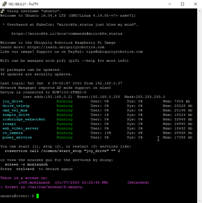
Below is the output when I ssh into the raspberry pi.  It shows:

– Wifi status and IP address
– Currently running ROS Node processes, and their mem and cpu status.  Colored Green for good, Red for stopped/crashed.
– Show that ‘rosmon’ is running on ‘screen’ and how to connect to it.
– The command line shows the current git status

rover_putty

I put this script in git in two parts – the first is a bash script to source from bash, and the second is a python script to use ros to get the current status.

See those links for the source code.  I think that every ROS project can benefit from these.

Boogie Rocker Design

Ultrasonic Sensor

I played about with making a robot face.  I combined a Ultrasonic Sensor (HC-SR04) and NeoPixel leds.  The leds reflect the distance – one pixel per 10 of cm.

I’m wondering if I can do SLAM – Simultaneous Location And Mapping  with a single (or a few) very-cheap ultrasonic sensor. Well, the answer is almost certainly no, but I’m very curious to see how far I can get.

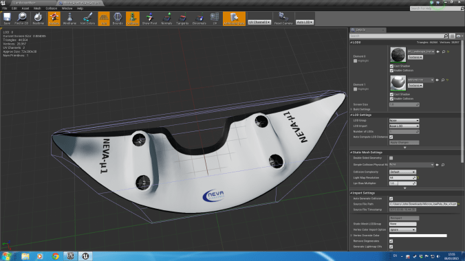
NOTE: This is an old design – from more than two years ago

face2

Advertisement

Flight aerodynamics simulator

I wanted to have a modern aerodynamics simulator, to test out my flight control hardware and software.

Apologies in advance for a very terse post.  I spent a lot of hours in a very short timespan to do this as a quick experiment.

So I used Unreal Engine 4 for the graphics engine, and built on top of that.

The main forces for a low speed aircraft that I want to model:

  1. The lift force due to the wing
  2. The drag force due to the wind
  3. Gravity
  4. Any horizontal forces from propellers in aircraft-style propulsion
  5. Any vertical forces from propellers in quadcopter-style propulsion

Lift force due to the wing

The equation for the lift force is:

L = C_l \cdot A \cdot .5 \cdot r \cdot V^2

I created a function for the lift coefficient, C_l, based on the angle, by calculating it theoretically.  To get proper results, I would need to actually measure this in a wind tunnel, but this is good enough for a first approximation:
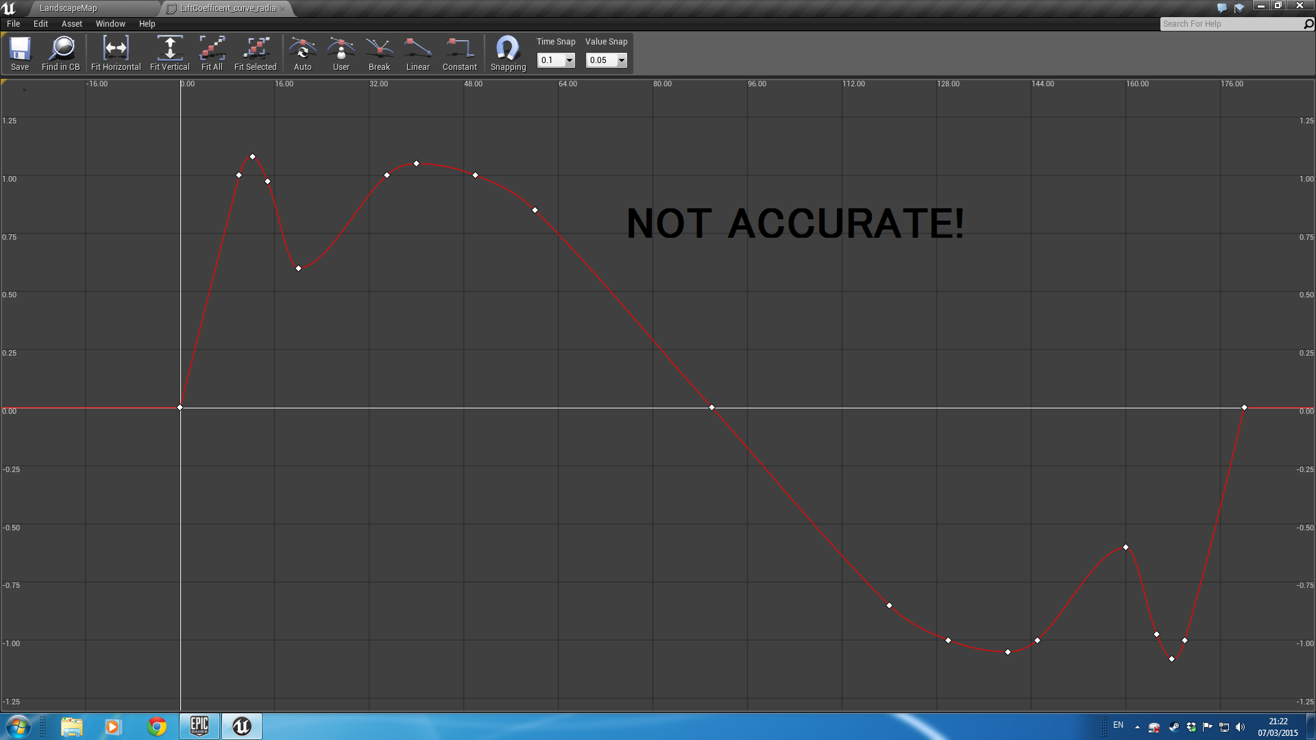
micron lift coefficients

The horizontal axis is the angle of attack, in degrees.  When the aircraft is flying “straight”, the angle of attack is not usually 0, but around 5 to 10 degrees, thus still providing an upward force.

I repeat this for each force in turn.

3D Model

To visualize it nicely, I modelled the craft in blender, manually set the texture space, and painted the texture in gimp.  As you can tell from the texture space, there are several horrible problems with the geometry ‘loops’.  But it took a whole day to get the top and bottom looking decent, and it was close enough for my purposes.


I imported the model into Unreal Engine 4, and used a high-resolution render for the version in the top right, and used a low-resolution version for the game. screenshot2

textured_micron_screenshot

Next, here’s the underneath view.  You can see jagged edges in the model here, because at the time I didn’t understand how normal smoothing worked.  After a quick google, I selected those vertexes in blender and enabled normal smoothing on them and fixed that.

ue4_2(1)

and then finally, testing it out on the real thing:

Screenshot_20180626_232400

Screenshot_20180626_232350

Architecture

The architecture is a fairly standard Hardware-in-loop system.

The key modules are:

simulator

  • The Flight Controller which controls the craft.  This is not used if we are connected to external real hardware, such as the my controller.
  • The Communication Module to the real hardware, receiving information about the desired thrust of the engines and the Radio Control inputs from the user, and sending information about the current simulated position and speed.
  • The Physics Simulator which calculates the physical forces on the craft and applies them.
  • The User Interface which displays a lot of information about the craft as well as the internal controller.

The low level flight controller and network communication code is written in C++.  Much of the high level logic is written in a visual language called ‘Blueprint’.

User Interface

From the GUI User Interface, you can control:

  • The aerodynamic forces on the wings
  • The height above ground to air pressure curve
  • The wing span and aerofoil chord length
  • The moment of inertia
  • The thrust of the turbines
  • The placement of the turbines
  • The PID values for the internal controller

Result

It worked pretty well.

It uses Hardware-In-Loop to allow the real hardware to control this, including a RC-Transmitter.
In this video I am allowing the PID algorithms to control the roll, pitch, yaw and height, which I then add to in order to control it.


PID Tuning

I implemented an auto-tuner for the PID algorithm, which you can tune and trigger from the GUI.

 Hardware

I used two arduinos to control the system:

overview

And set up the Arduinos as so:  (Btw, I used the Fritzing software for this – it’s pretty cool).

neva arduino_bb(1)


And putting together the hardware for testing (sorry for the mess).  (I’m using QGroundControl to test it out).

And then mounting the hardware on a bit of wood as a base to keep it all together and make it more tidy:

20140822_202401.jpg

I will hopefully later make a post about the software controlling this.

ESC Motor Controller Delay

I was particularly worried about the delay that the controller introduces.

I modified the program and used a basic UFO style quadcopter, then added in a 50ms buffer, to test the reaction.

For reference, here’s a photo of the real thing that I work on:

The quadcopter is programmed to try to hover over the chair.


I also tested with different latencies:


50ms really is the bare minimum that you can get away with.

These are manually tuned PIDs.

I did also simulate this system in 1D in Matlab’s Simulink:

simulink_roll

A graph of the amplitude:

matlab estimated transfer function sin

And finally, various bode plots etc.  Just click on any for a larger image.  Again, apologies for the awful terseness.