Tensorflow for Neurobiologists

I couldn’t find anyone else that has done this, so I made this really quick guide.  This uses tensorflow which is a complete overkill for this specific problem, but I figure that a simple example is much easier to follow.

Install and run python3 notebook, and tensorflow.  In Linux, as a user without using sudo:

$ pip3 install --upgrade --user ipython[all] tensorflow matplotlib
$ ipython3  notebook

Then in the notebook window, do New->Python 3

Here’s an example I made earlier. You can download the latest version on github here: https://github.com/johnflux/Spike-Triggered-Average-in-TensorFlow

Spike Triggered Average in TensorFlow

The data is an experimentally recorded set of spikes recorded from the famous H1 motion-sensitive neuron of the fly (Calliphora vicina) from the lab of Dr Robert de Ruyter van Steveninck.

This is a complete rewrite of non-tensorflow code in the Coursera course Computational Neuroscience by University of Washington. I am thoroughly enjoying this course!

Here we use TensorFlow to find out how the neuron is reacting to the data, to see what causes the neuron to trigger.

%matplotlib inline
import pickle
import matplotlib.pyplot as plt
import numpy as np
import tensorflow as tf
sess = tf.InteractiveSession()

FILENAME = 'data.pickle'

with open(FILENAME, 'rb') as f:
    data = pickle.load(f)

stim = tf.constant(data['stim'])
rho = tf.constant(data['rho'])
sampling_period = 2 # The data was sampled at 500hz = 2ms
window_size = 150 # Let's use a 300ms / sampling_period sliding window

We now have our data loaded into tensorflow as a constant, which means that we can easily ‘run’ our tensorflow graph. For example, let’s examine stim and rho:

print("Spike-train time-series =", rho.eval(),
      "\nStimulus time-series     =", stim.eval())
Spike-train time-series = [0 0 0 ..., 0 0 0] 
Stimulus time-series    = [-111.94824219  -81.80664062 
    10.21972656 ...,  9.78515625 24.11132812 50.25390625]

rho is an binary array where a 1 indicates a spike. Let’s turn that into an array of indices of where the value is 1, but ignoring the first window_size elements.

Note: We can use the [] and + operations on a tensorflow variable, and it correctly adds those operations to the graph. This is equivalent to using the tf.slice and tf.add operations.

spike_times = tf.where(tf.not_equal(rho[window_size:-1], 0)) + window_size
print("Time indices where there is a spike:\n", spike_times.eval())
Time indices where there is a spike:
 [[   158]
 [   160]
 [   162]
 ..., 
 [599936]
 [599941]
 [599947]]
def getStimWindow(index):
    i = tf.cast(index, tf.int32)
    return stim[i-window_size+1:i+1]
stim_windows = tf.map_fn(lambda x: getStimWindow(x[0]), spike_times, dtype=tf.float64)
spike_triggered_average = tf.reduce_mean(stim_windows, 0).eval()
print("Spike triggered averaged is:", spike_triggered_average[0:5], "(truncated)")
Spike triggered averaged is: [-0.33083048 -0.29083503 -0.23076012 -0.24636984 -0.10962767] (truncated)

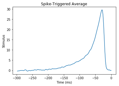
Now let’s plot this!

time = (np.arange(-window_size, 0) + 1) * sampling_period
plt.plot(time, spike_triggered_average)
plt.xlabel('Time (ms)')
plt.ylabel('Stimulus')
plt.title('Spike-Triggered Average')

plt.show()

output_8_0

It’s… beautiful!

What we are looking at here, is that we’ve discovered that our neuron is doing a leaky integration of the stimulus. And when that integration adds up to a certain value, it triggers.

Do see the github repo for full source: https://github.com/johnflux/Spike-Triggered-Average-in-TensorFlow

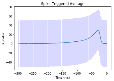
Update: I was curious how much noise there was. There’s a plot with 1 standard deviation in light blue:

mean, var = tf.nn.moments(stim_windows,axes=[0])
plt.errorbar(time, spike_triggered_average, yerr=tf.sqrt(var).eval(), ecolor="#0000ff33")

spike2

Yikes!  This is why the input signal MUST be Gaussian, and why we need lots of data to average over.  For this, we’re averaging over 53583 thousand windows.

3D Camera Recording Software in React

This is project that I’ve been working on for the past 6 months.  We are now officially selling the software, so I wanted to give a brief overview of how I implemented this.  There’s no secrets here – nothing here that you couldn’t work out easily from looking at the site.

I implemented the front end in React + Redux in Javascript using a websocket and RESTful API for communication.  I worked with a UI designer and a team that implemented the backend.

Some quick lessons learned:

  • React is really nice 🙂
  • I initially implemented the gamma correction graphs in HTML 5 Canvas, but found it difficult to get it to look nice on high density displays.  I switched to creating SVGs instead.
  • Modifying SVGs on the fly using React is really really nice!
  • I initially developed without using Redux, but was eventually persuaded into switching to Redux.  Honestly, I’m really not convinced it was the right choice.  Dan Abramov, the co-author of Redux, wrote an article called: “You might not need Redux” which I agree with.
  • I intended from the start to have a “fake backend” that acted like a simulator of the feel hardware and used the same websocket protocol.  This turned out to be extremely useful, and paid itself back over and over.
  • Keep in touch with the end users as much as possible, and release early and release often.  There’s a lot of hate for the word ‘Agile’, but I’ve used it in 3 major projects so far, and I’m a true believer in it.
  • Visual Studio Code (not Visual Studio) works in Linux flawlessly and is absolutely awesome.  It’s won me over after being a heavy vim user for 15 years.  It supports ES7 and JSX syntax.
  • Javascript lint is awesome, even though at the start the rules seem totally ridiculous.  (e.g. you have to have colors in uppercase in the css).  The rules still feel ridiculous, but it doesn’t take long to just do it the way lint wants.
  • Don’t go for a minimal react setup, but use a boilerplate with the most common things included, such as this.  It can seem really heavy for a beginner, but things like babel, router, image loader, ES7, etc are just awesome.


Converting LED solar powered garden lights for a doll’s house

I bought a solar panel from China and three solar-powered garden lights for $0.85 USD each.  I opened up the garden lights, and inside was a really simple circuit with a single chip to boost the voltage from the 1.2V battery to the 3V needed for the LED, and an inductor to control the amount of current that it supplies:

One of the garden lights wasn’t working, so that left me with two.  I cut off the small solar panels from the two remaining garden light circuit boards, and connected them in parallel to the larger solar panel that I’d bought.   I cut off the LED and inductor from the broken board, and soldered them in parallel to a working board’s LED and inductor, respectively.  For the upstairs LED, I actually cut off the white LED and used a yellow LED, just to make it seem more cozy like a bedroom.

I wired it all up, and hot glued everything into place.

The inductance controls the current supplied by the YX8018 booster to the LED, and from its spec sheet, an inductance of 220uH gives us 7 mA to the LED.  By putting two in parallel, we get a total inductance of 1/(2/220uH) = 220uH/2 = 110uH.  Which from the spec sheet gives us 10mA.  Which is good enough.

So in total, we draw 3V x 10mA = 0.03 watts for the LEDs.  Perhaps round that up to 0.05 to include the booster circuit.  So drawing 25mA from the 1.2V cells.

And so, the result is three LEDs which light up when it’s dark, and stays lit for several hours (2 days if the cells actually hold 2*600mAh like they say on them, but I don’t believe that value in the slightest).


Biped Robot

I’ve always wanted to make a walking robot.  I wanted to make something fairly rapidly and cheaply that I could try to get walking.

And so, 24 hours of hardware and software hacking later:

8jiqqy

He’s waving only by a short amount because otherwise he falls over 🙂  Took a day and half to do, so overall I’m pretty pleased with it.  It uses 17 MG996R servos, and a Chinese rtrobot 32 servo controller board.

Reverse Engineering Servo board

The controller board amazingly provides INCOMPLETE instructions.  The result is that anyone trying to use this board will find that it just does not work because the board completely ignores the commands that are supposed to work.

I downloaded the example software that they provide, which does work.  I ran the software through strace like:

$ strace  ./ServoController 2>&1 | tee dump.txt

Searching in dump.txt for ttyACM0 reveals the hidden initialization protocol.  They do:

open("/dev/ttyACM0", O_RDWR|O_NOCTTY|O_NONBLOCK) = 9
write(9, "~RT", 3)                      = 3
read(9, "RT", 2)                        = 2
read(9, "\27", 1)                       = 1
ioctl(9, TCSBRK, 1)                     = 0
write(9, "~OL", 3)                      = 3
write(9, "#1P1539\r\n", 9)              = 9

(The TCSBRK  ioctl basically just blocks until nothing is left to be sent).  Translating this into python we get:


#!/usr/bin/python
import serial
from time import sleep

ser = serial.Serial('/dev/ttyACM0', 9600)
ser.write('~RT')
print(repr(ser.read(3)))
ser.write('~OL')
ser.flush()
ser.write("#1P2000\r\n")  # move motor 1 to 2000
sleep(1)
ser.write("#1P1000\r\n")  # move motor 1 to 1000
print("done")

(Looking at the strace more, running it over multiple runs, sometimes it writes “~OL” and sometimes “OL”.  I don’t know why.  But it didn’t seem to make a difference.  That’s the capital letter O btw.)

Feedback

I wanted to have a crude sensor measurement of which way up it is.  After all, how can it stand up if it doesn’t know where up is?  On other projects, I’ve used an accelerometer+gyro+magnetometer, and fused the data with a kalman filter or similar.  But honestly it’s a huge amount of work to get right, especially if you want to calibrate them (the magnetometer in particular).  So I wanted to skip all that.

Two possible ideas:

  1. There’s a really quick hack that I’ve used before – simply place the robot underneath a ceiling light, and use a photosensitive diode to detect the light (See my Self Balancing Robot).  Thus its resistance is at its lowest when it’s upright 🙂   (More specifically, make a voltage divider with it and then measure the voltage with an Arduino).  It’s extremely crude, but the nice thing about it is that it’s dead cheap, and insensitive to vibrational noise, and surprisingly sensitive still.  It’s also as fast as your ADC.
  2. Use an Android phone.

I want to move quickly on this project, so I decided to give the second way a go.  Before dealing with vibration etc, I first wanted to know whether it could work, and what the latency would be if I just transmitted the Android fused orientation data across wifi (UDP) to my router, then to my laptop, which then talks via USB to the serial board which then finally moves the servo.

So, I transmitted the data and used the phone tilt to control the two of the servos on the arm, then recorded with the same phone’s camera at the same time.   The result is:

I used a video editor (OpenShot) to load up the video, then measured the time between when the camera moved and when the arm moved.  I took 6 such measurements, and found 6 or 7 frames each time – so between 200ms and 233ms.

That is..  exactly what TowerKing says is the latency of the servo itself (Under 0.2s).  Which means that I’m unable to measure any latency due to the network setup.  That’s really promising!

I do wonder if 200ms is going to be low enough latency though (more expensive hobby servos go down to 100ms), but it should be enough.  I did previously do quite extensive experimental tests on latency on the stabilization of a PID controlled quadcopter in my own simulator, where 200ms delay was found to be controllable, but not ideal.  50ms was far more ideal.  But I have no idea how that lesson will transfer to robot stabilization.

But it is good enough for this quick and dirty project.  This was done in about 0.5 days, bringing the total so far up to 2 full days of work.

Cost and Time Breakdown so far

Metal skeleton $99 USD
17x MG996R servo motors $49 USD
RT Robot 32ch Servo control board $25 USD
Delivery from China $40 USD
USB Cable $2 USD
Android Phone (used own phone)
Total: $215 USD
Parts cost:

For tools, I used nothing more than some screwdrivers and needle-nosed pliers, and a bench power supply. Around $120 in total. I could have gotten 17x MG995 servos for a total of $45, but I wanted the metal gears that the MG996R provide.

Time breakdown:
Mechanical build 1 day
Reverse engineering servo board 0.5 days
Hooking up to Android phone + writing some visualization code 0.5 days
Blogging about it 🙂 0.5 days
Total: 2.5 days

Future Plans – Q Learning

My plan is to hang him loosely upright by a piece of string, and then make a neural network in tensor flow to control him to try to get him to stand full upright, but not having to deal with recovering from a collapsed lying-down position.

Specifically, I want to get him to balance upright using Q learning.  One thing I’m worried about is the sheer amount of time required to physically do each tests.  When you have a scenario where each test takes a long time compared to the compute power, this just screams out for Bayesian learning.   So…  Bayesian Q-parameter estimation?  Is there such a thing?  A 10 second google search doesn’t find anything.  Or Bayesian policy network tuning?    I need to have a think about it 🙂

Coursera Neural Networks for Machine Learning

I’ve completed another 4 month Coursera Machine Learning course. The first was the Andrew NG’s Machine Learning course, and the second is Geoffrey Hinton’s Neural Networks for Machine Learning course.  I also completed a 2 month Coursera course in Computation Neuroscience.

coursera.png

Course certificate

Both courses use Matlab, and this second one was significantly more work and buggier. Several of the exam questions had key bits of information accidentally left out and referred to images that didn’t exist. Only by referring to the user forums could the key bits of information be found out. However I was one of the first people to do this course, so bugs are to be expected.

Technical issues aside, I enjoyed the course a lot. It’s approximately 5 years behind the current state of the field, but the information is still very relevant.

Edit: Update on 2017/2/5 – I also did the 2 month Computational Neuroscience course:

coursera

I enjoyed the first half of the course, which was all new and interesting to me.  But the second half was just a basic version of the Andrew Ng course.


React + Twine

Twine is a neat ‘open-source tool for telling interactive, nonlinear stories’, as its blurb says.  It lets you write stories using variables, conditionals, and other simple programming primitives.  It supports three different languages, but I’ll focus only on the default, Harlowe.  Some example code:

Hello $name. (if: $isMale)[You're male!](else:)[You're female!].

This works pretty well, but it can be really cumbersome to do anything complicated.  I was curious to see how well it could be integrated into React.  Harlowe purposefully does not expose any of its internals, so our solution is going to need to be pretty hacky.

The solution that I came up with was to add some javascript to a startup tag that Harlowe will run, and attach the necessary private variable to the global window variable.  Then to load and run the Harlowe engine in the react componentWillMount function.  Like so:

import React, { Component } from 'react';
import './App.css';

class App extends Component {
  componentWillMount() {
    const script = document.createElement("script");
    script.src = "harlowe-min.js";
    script.async = true;
    document.body.appendChild(script);
  }

  render() {
    return (
<div className="App">
        <header id="header">My header

</header>
<div id="container">
          <main id="center" className="column">
            <article>
              <tw-story dangerouslySetInnerHTML={{__html: ""}}></tw-story>
              <tw-storydata startnode={1} style={{display:"none"}}>
                <script role="script" id="twine-user-script" type="text/twine-javascript">{`
                  if (!window.harlowe){ window.harlowe = State; }
                `}</script>
                <tw-passagedata pid={1} name="Start">**Success!**(set: $foo to 1) Foo is $foo</tw-passagedata>
              </tw-storydata>
            </article>
          </main>

          <nav id="left" className="column">
<h3>Left heading</h3>
<ul>
	<li><a href="#">Some Link</a></li>
</ul>
</nav>
<div id="right" className="column">
<h3>Right heading</h3>
</div>
</div>
<div id="footer-wrapper">
          <footer id="footer">&nbsp;

</footer></div>
</div>
);
  }
}

export default App;

It seemed to work just fine without

dangerouslySetInnerHTML={{__html: ""}}

But I added it to make it clear to react that we don’t want react to manage this.

Unfortunately I couldn’t proceed further than this with trying to make them nicely integrate. I couldn’t see a way to hook into the engine to know when a variable is updated via, say, a user clicking on a (link:..)[].

There is a VarRef object that would allow exactly this with jQuery, by doing something like:

var setState = this.setState.bind(this);
VarRef.on('set', (obj, name, value) => {
  if (obj === State.variables) {
    setState({[name]: value})
  }
})

Unfortunately the VarRef is not exposed in any scope that I can find. The source code is available, so the VarRef can be exposed with a fairly simple change, but not without doing that, as far I can tell.

Changing the color of image in HTML with an SVG feColorMatrix filter

In a previous post, I changed the color of a simple image (of a pair of eyes) by converting it to an SVG first, and then changing the SVG colors.

But what if you want to a take a complex image and change the color?


In Photoshop/Gimp this can be achieved by creating a new layer on top of the image and filling it with a solid color, and then setting its Mode to ‘Multiply’.  But how can we reproduce this on the web?

There are various solutions using svg filters (feFlood and feBlend) but these are not very well supported in browsers.  So I’ve come up with a solution that is very well supported in all modern browsers, including IE.


...


Replace the numbers 0.5 with the rgb values of the color that you want.  For example, in react:


hexToRgb(hex) {
var result = /^#?([a-f\d]{2})([a-f\d]{2})([a-f\d]{2})$/i.exec(hex);
return result ? {
r: parseInt(result[1], 16),
g: parseInt(result[2], 16),
b: parseInt(result[3], 16)
} : {r: 255, g: 255, b: 255};
}

skinColorDef(colorAsString) {
const hex = hexToRgb(colorAsString); /* <-- See next for an improvement*/
const r = hex.r/255;
const g = hex.g/255;
const b = hex.b/255;
return (


);
}


We can now tint our image with a color like skinColorDef(“#e7b48f”).

But let’s make small improvement.  It’s not obvious what the final color is going to be because the tint color is multiplied by the color in the image.  So let’s make it more intuitive by first looking at the main color in the image (e.g. using the color picker in gimp/photoshop) and then dividing (i.e ‘un-multiplying’) the colorAsString by that color.

For example, the skin color in that girl image is #fff2f2 which is (255,242,228).  So:


divideByImageSkinColor(rgb) {
return {r: rgb.r * (255/255), g: rgb.g * (255/242), b: rgb.b * (255/242)}
}

and modify the skinColorDef like:


skinColorDef(colorAsString) {
const hex = divideByImageSkinColor(hexToRgb(colorAsString));

Now we can just chose the colors directly.  For skin, the Fitzpatrick Scale is a nice place to start:

fitzpatrick-color-chart

We can now use these RGB values directly in our skinColorDef function.  Here’s an example html combobox to select the color: (The onChange function is left to you to implement)


Light
Fair
Medium
Olive
Brown
Black


And that’s it!

Sidenote: Many years ago, I wrote the graphics drivers (when I worked at Imagination Technologies) to accelerate this sort of multiply operation using shaders.  That driver is used in the iPhone, iPad, TomTom, and many other small devices.

Photoshop/gimp layers to SVG

Ever wanted to export multiple layers in a Gimp or Photoshop image, with each layer as its own PNG, but the whole thing then wrapped up as an SVG?

The usefulness is that an artist can create an image of, say, a person, with eyes of various different colours in multiple layers.  Then we can create an SVG file that we can embed in an html page, and then change the color of the eyes through Javascript.

So take this example.  In this image we have a face made up of various layers, and the layers are further grouped in GroupLayers.

So imagine having this image, then in Javascript on your page being able to swap out just the eye image.  Or just the mouth image.

To achieve this, I had to modify an existing gimp python script from 5 years ago that has since bitrotted.  Back when it was written, there was no such thing as group layers, so the script doesn’t work now.  A bit of hacking, and I get:

#!/usr/bin/env python
# -*- coding: <utf-8> -*-
# Author: Erdem Guven <zuencap@yahoo.com>
# Copyright 2016 John Tapsell
# Copyright 2010 Erdem Guven
# Copyright 2009 Chris Mohler
# "Only Visible" and filename formatting introduced by mh
# License: GPL v3+
# Version 0.2
# GIMP plugin to export as SVG

# Save this to ~/.gimp-*/plug-ins/export_svg.py

from gimpfu import *
import os, re

gettext.install("gimp20-python", gimp.locale_directory, unicode=True)

def format_filename(imagename, layer):
	layername = layer.name.decode('utf-8')
	regex = re.compile("[^-\w]", re.UNICODE)
	filename = imagename + '-' + regex.sub('_', layername) + '.png'
	return filename

def export_layers(dupe, layers, imagename, path, only_visible, inkscape_layers):
	images = ""
	for layer in layers:
		if not only_visible or layer.visible:
			style=""
			if layer.opacity != 100.0:
				style="opacity:"+str(layer.opacity/100.0)+";"
			if not layer.visible:
				style+="display:none"
			if style != "":
				style = 'style="'+style+'"'

			if hasattr(layer,"layers"):
				image = '<g inkscape:groupmode="layer" inkscape:label="%s" %s>' % (layer.name.decode('utf-8'),style)
				image += export_layers(dupe, layer.layers, imagename, path, only_visible, inkscape_layers)
				image += '</g>'
				images = image + images
			else:
				filename = format_filename(imagename, layer)
				fullpath = os.path.join(path, filename);
				pdb.file_png_save_defaults(dupe, layer, fullpath, filename)

				image = ""
				if inkscape_layers:
					image = '<g inkscape:groupmode="layer" inkscape:label="%s" %s>' % (layer.name.decode('utf-8'),style)
					style = ""
				image += ('<image xlink:href="%s" x="%d" y="%d" width="%d" height="%d" %s/>\n' %
					(filename,layer.offsets[0],layer.offsets[1],layer.width,layer.height,style))
				if inkscape_layers:
					image += '</g>'
				images = image + images
		dupe.remove_layer(layer)
	return images

def export_as_svg(img, drw, imagename, path, only_visible=False, inkscape_layers=True):
	dupe = img.duplicate()

	images = export_layers(dupe, dupe.layers, imagename, path, only_visible, inkscape_layers)

	svgpath = os.path.join(path, imagename+".svg");
	svgfile = open(svgpath, "w")
	svgfile.write("""<?xml version="1.0" encoding="UTF-8" standalone="no"?>
<!-- Generator: GIMP export as svg plugin -->

<svg xmlns:xlink="http://www.w3.org/1999/xlink" """) 	if inkscape_layers: 		svgfile.write('xmlns:inkscape="http://www.inkscape.org/namespaces/inkscape" ') 	svgfile.write('width="%d" height="%d">' % (img.width, img.height));
	svgfile.write(images);
	svgfile.write("</svg>");

register(
	proc_name=("python-fu-export-as-svg"),
	blurb=("Export as SVG"),
	help=("Export an svg file and an individual PNG file per layer."),
	author=("Erdem Guven <zuencap@yahoo.com>"),
	copyright=("Erdem Guven"),
	date=("2016"),
	label=("Export as SVG"),
	imagetypes=("*"),
	params=[
		(PF_IMAGE, "img", "Image", None),
		(PF_DRAWABLE, "drw", "Drawable", None),
		(PF_STRING, "imagename", "File prefix for images", "img"),
		(PF_DIRNAME, "path", "Save PNGs here", os.getcwd()),
		(PF_BOOL, "only_visible", "Only Visible Layers?", False),
		(PF_BOOL, "inkscape_layers", "Create Inkscape Layers?", True),
		   ],
	results=[],
	function=(export_as_svg),
	menu=("<Image>/File"),
	domain=("gimp20-python", gimp.locale_directory)
	)

main()

(Note that if you get an error ‘cannot pickle GroupLayers’, this is a bug in gimp. It can be fixed by editing

    350: gimpshelf.shelf[key] = defaults

)

Which when run, produces:

girl-Layer12.png
girl-Layer9.png
girl-Layer11.png
girl-Layer14.png
girl.svg

(I later renamed the layers to something more sensible 🙂 )

The (abbreviated) svg file looks like:


<g inkscape:groupmode="layer" inkscape:label="Expression" >

<g inkscape:groupmode="layer" inkscape:label="Eyes" >

<g inkscape:groupmode="layer" inkscape:label="Layer10" ><image xlink:href="girl-Layer10.png" x="594" y="479" width="311" height="86" /></g>

<g inkscape:groupmode="layer" inkscape:label="Layer14" ><image xlink:href="girl-Layer14.png" x="664" y="470" width="176" height="22" /></g>

<g inkscape:groupmode="layer" inkscape:label="Layer11" ><image xlink:href="girl-Layer11.png" x="614" y="483" width="268" height="85" /></g>

<g inkscape:groupmode="layer" inkscape:label="Layer9" ><image xlink:href="girl-Layer9.png" x="578" y="474" width="339" height="96" /></g>

<g inkscape:groupmode="layer" inkscape:label="Layer12" ><image xlink:href="girl-Layer12.png" x="626" y="514" width="252" height="30" /></g>

</g>

</g>

We can now paste the contents of that SVG directly into our html file, add an id to the groups or image tag, and use CSS or Javascript to set the style to show and hide different layers as needed.

CSS Styling

This all works as-is, but I wanted to go a bit further.  I didn’t actually have different colors of the eyes.  I also wanted to be able to easily change the color.  I use the Inkscape’s Trace Bitmap to turn the layer with the eyes into a vector, like this:

girl-eyecolor

Unfortunately, WordPress.com won’t let me actually use SVG images, so this is a PNG of an SVG created from a PNG….

I used as few colors as possible in the SVG, resulting in just 4 colors used in 4 paths.  I manually edited the SVG, and moved the color style to its own tag, like so:


<defs>
<style type="text/css"><![CDATA[ #eyecolor_darkest { fill:#34435a; } #eyecolor_dark { fill:#5670a1; } #eyecolor_light { fill:#6c8abb; } #eyecolor_lightest { fill:#b4dae5; } ]]></style>

</defs>

<path id="eyecolor_darkest" ..../>

The result is that I now have an svg of a pair of eyes that can be colored through css.  For example, green:

girl-eyecolor_green

Which can now be used directly in the head svg in an html, and styled through normal css:

head_green

Colors

For the sake of completeness, I wanted to let the user change the colors, but not have to make them specify each color individually. I have 4 colors used for the eye, but they are obviously related. Looking at the blue colors in HSL space we get:

RGB:#34435a =  hsl(216, 27%, 28%)
RGB:#5670a1 =  hsl(219, 30%, 48%)
RGB:#6c8abb =  hsl(217, 37%, 58%)
RGB:#b4dae5 =  hsl(193, 49%, 80%)

Annoyingly, the lightest color has a different hue. I viewed this color in gimp, change the hue to 216, then tried to find the closest saturation and value that matched it. 216, 85%, 87% seemed the best fit.

So, armed with this, we now have a way to set the color of the eye with a single hue:

#eyecolor_darkest  =  hsl(hue, 27%, 28%)
#eyecolor_dark     =  hsl(hue, 30%, 48%)
#eyecolor_light    =  hsl(hue, 37%, 58%)
#eyecolor_lightest =  hsl(hue, 85%, 87%)

Or in code:

function setEyeColorHue(hue) {
    document.getElementById("eyecolor_darkest").style.fill = "hsl("+hue+", 27%, 28%)";
    document.getElementById("eyecolor_dark").style.fill = "hsl("+hue+", 30%, 48%)";
    document.getElementById("eyecolor_light").style.fill = "hsl("+hue+", 37%, 58%)";
    document.getElementById("eyecolor_lightest").style.fill = "hsl("+hue+", 85%, 87%)";
}
<label for="hue">Color:</label>
<input type="range" id="hue" min="0" value="216" max="359" step="1" oninput="setEyeColorHue(this.value)" onchange="setEyeColorHue(this.value)"/>

Tinting a more complex image

But what if the image is more complex, and you don’t want to convert it to an SVG?  E.g.

The solution is to apply a filter to multiply the layer by another color.

See my follow up post: Changing the color of image in HTML with an SVG feColorMatrix filter


Dilation Animation

There is a neat git repository that generates animations of various different settings. But unfortunately it didn’t show dilation – which is one of my favourite Convolutional Neural Network techniques.

Edit: My changes are now merged

So I added support.

And here’s what my patch generates:  The bottom layer is the input layer, the top is the output layer.

dilation

No stride, no padding, dilation of 2, kernel size of 3

The idea with dilation is that at each layer you double the dilation size.  That way your receptive field grows exponentially with each layer, allowing you to deal with large images without pooling and thus have pixel sharpness.